
Switch for use in microelectromechanical systems (MEMS) and MEMS devices incorporating same

a microelectromechanical system and switch technology, applied in relays, generators/motors, contacts, etc., can solve the problems of degrading the electrical performance of the switch, affecting the performance and/or life of the switch, and effectively destroying the system, etc., to achieve the effect of improving performance and li

Inactive Publication Date: 2009-10-22
FORMFACTOR INC
View PDF82 Cites 15 Cited by
  • Summary
  • Abstract
  • Description
  • Claims
  • Application Information

AI Technical Summary

Benefits of technology

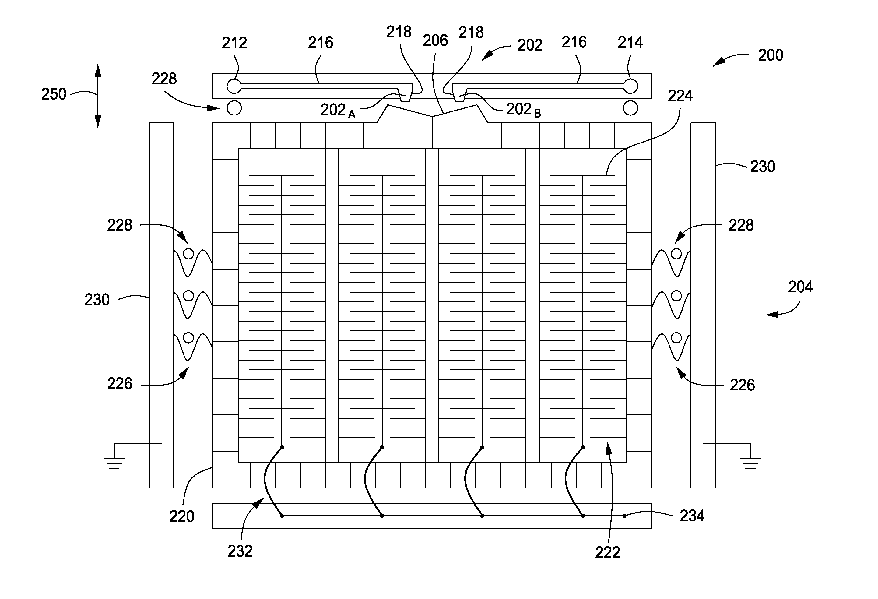
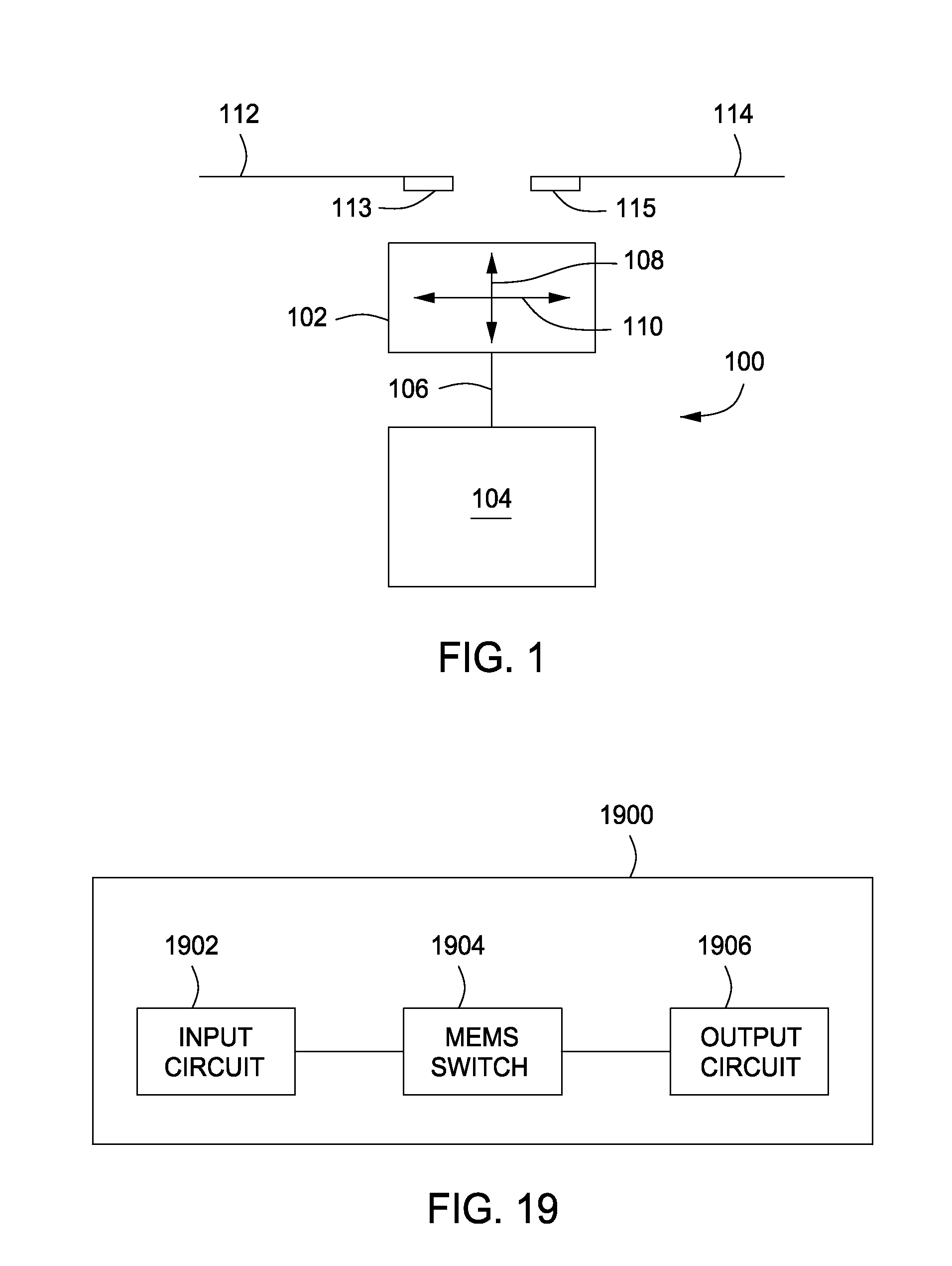
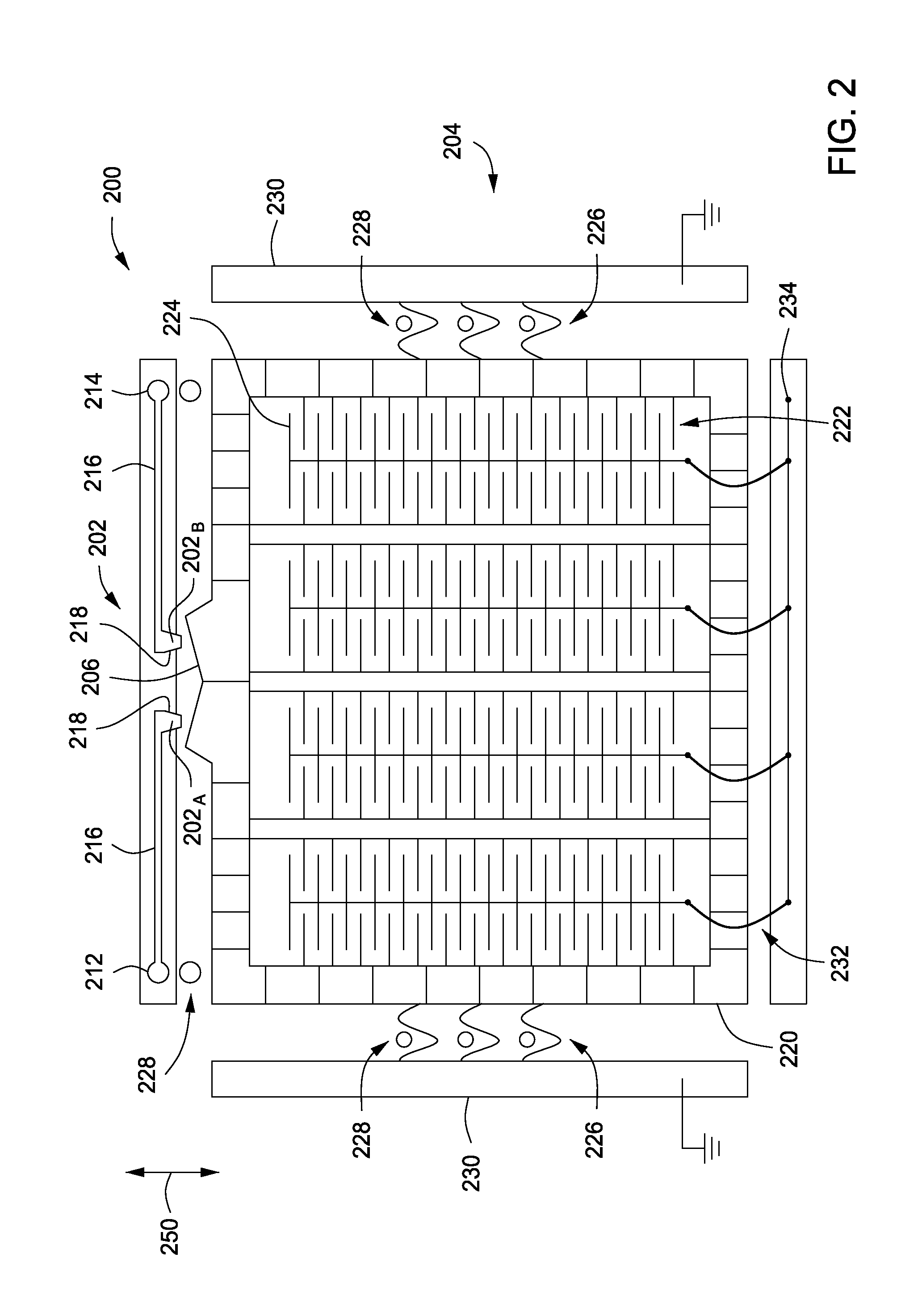
[0006]Embodiments of the present invention provide microelectromechanical systems (MEMS) switching methods and apparatus having improved performance and lifetime as compared to conventional MEMS switches. In some embodiments, a MEMS switch may include a resilient contact element comprising a beam and a tip configured to wipe (i.e., providing a wiping motion across) a contact surface; and a MEMS actuator having an open position that maintains the tip and the contact surface in a spaced apart relation and a closed position that brings the tip into contact with the contact surface, wherein the resilient contact element and the MEMS actuator are disposed on a substrate and are movable in a plane substantially parallel to the substrate. In some embodiments, various contact elements are provided for the MEMS switch. In some embodiments, various actuators are provided for control of the operation of the MEMS switch.

Problems solved by technology

Such switches are typically expected to have a fixed lifetime, such that any problem that interferes with the operation or performance of the switch typically effectively destroys the system.
For example, the electrical performance of the switch may be degraded due to oxidation of the contacts of the switch.
In addition, contact pad wear due to switch operation may also degrade the performance and / or the life of the switch.
Further, particles or other contaminants may also interfere with switch performance.

Method used


Image

  • Switch for use in microelectromechanical systems (MEMS) and MEMS devices incorporating same
  • Switch for use in microelectromechanical systems (MEMS) and MEMS devices incorporating same
  • Switch for use in microelectromechanical systems (MEMS) and MEMS devices incorporating same

Examples


Embodiment Construction

[0033]This specification describes exemplary embodiments and applications of the invention. The invention, however, is not limited to these exemplary embodiments and applications or to the manner in which the exemplary embodiments and applications operate or are described herein. In addition, as the terms “on” and “attached to” are used herein, one object (e.g., a material, a layer, a substrate, etc.) can be “on” or “attached to” another object regardless of whether the one object is directly on or attached to the other object or there are one or more intervening objects between the one object and the other object. Also, directions (e.g., above, below, top, bottom, side, up, down, “x,”“y,”“z,” etc.), if provided, are relative and provided solely by way of example and for ease of illustration and discussion and not by way of limitation. In addition, where reference is made to a list of elements (e.g., elements a, b, c), such reference is intended to include any one or more of the lis...


PUM


Abstract

Embodiments of the present invention provide microelectromechanical systems (MEMS) switching methods and apparatus having improved performance and lifetime as compared to conventional MEMS switches. In some embodiments, a MEMS switch may include a resilient contact element comprising a beam and a tip configured to wipe a contact surface; and a MEMS actuator having an open position that maintains the tip and the contact surface in a spaced apart relation and a closed position that brings the tip into contact with the contact surface, wherein the resilient contact element and the MEMS actuator are disposed on a substrate and are movable in a plane substantially parallel to the substrate. In some embodiments, various contact elements are provided for the MEMS switch. In some embodiments, various actuators are provided for control of the operation of the MEMS switch.

Description

BACKGROUND OF THE INVENTION[0001]1. Field of the Invention[0002]The present invention generally relates to microelectromechanical systems (MEMS), and more particularly, to switches used in MEMS devices.[0003]2. Description of the Related Art[0004]Many systems, such as semiconductor testing systems, electronic circuits, microelectromechanical systems (MEMS), or the like (as non-limiting examples), often utilize switches to selectively make contacts to route electrical signals through the systems to facilitate the use and / or control thereof. Such switches are typically expected to have a fixed lifetime, such that any problem that interferes with the operation or performance of the switch typically effectively destroys the system. For example, the electrical performance of the switch may be degraded due to oxidation of the contacts of the switch. In addition, contact pad wear due to switch operation may also degrade the performance and / or the life of the switch. Further, particles or o...

Claims


Application Information

Patent Timeline
Patent Type & Authority Applications(United States)
IPC IPC(8): H01H59/00H02N1/00
CPCH01H1/0036H01H1/60H01H2001/0078H01H2001/0047H01H2001/0052H01H59/0009
Inventor GRITTERS, JOHN K.HOBBS, ERIC D.PARK, SANGTAEYAO, JUN JASON
Owner FORMFACTOR INC
Learn More