Travel drive device for dump truck
a technology for traveling drive and dump trucks, which is applied in the direction of gearing details, gearing, transportation and packaging, etc., can solve the problems of lack of lubrication and insufficient strength of the spline-coupling portion, and achieve the effects of increasing the strength of the rotational load, enhancing the durability and the lifetime of the entire travel drive device, and enhancing the durability and reliability of the entire devi
- Summary
- Abstract
- Description
- Claims
- Application Information
AI Technical Summary
Benefits of technology
Problems solved by technology
Method used
Image
Examples
first embodiment
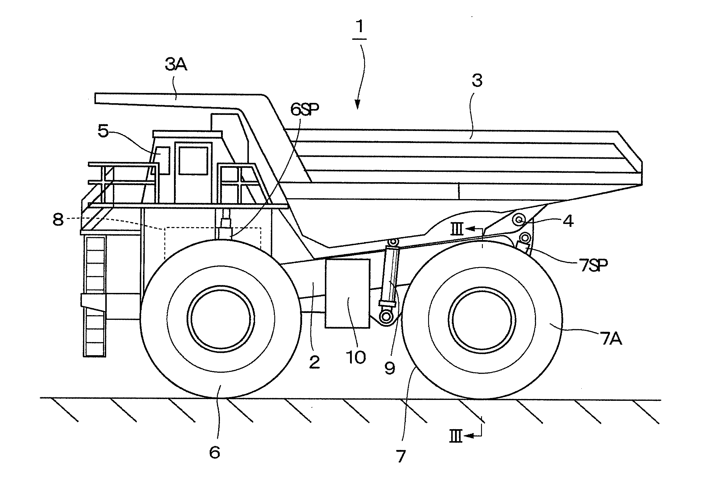
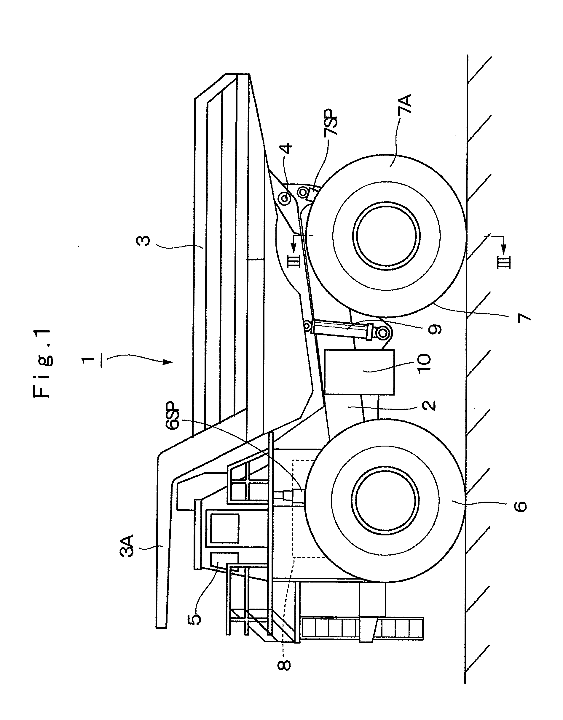
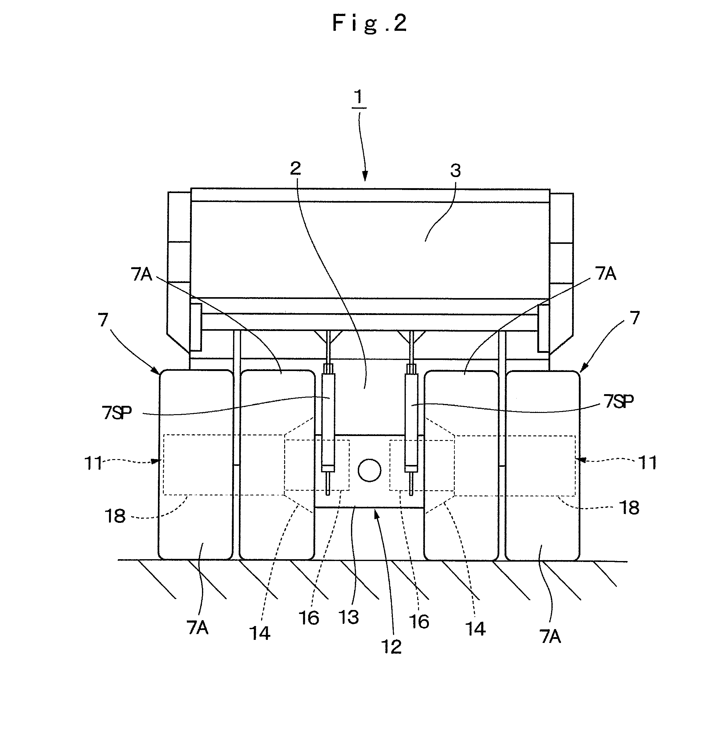
[0036]FIG. 1 to FIG. 5 show a travel drive device for a dump truck in the present invention.
[0037]In the figure, designated at 1 is a dump truck of a large-sized transporter vehicle adopted in the first embodiment. The dump truck 1 is constituted by including a vehicle body 2 having a strong frame structure and a vessel 3 as a loading platform liftably mounted on the vehicle body 2.
[0038]The vessel 3 is formed, for example, as a large-sized container of an entire length of 9 to 13 meters for loading a large volume of heavy baggage such as crushed stones. A rear-side bottom portion of the vessel 3 is liftably (tiltably) connected to a rear end side of the vehicle body 2 through a connecting pin 4. A protector 3A is integrally provided in a front-side top portion of the vessel 3 in such a manner as to cover a cab 5 to be described later from the upper side.
[0039]The cab 5 is provided in the front portion of the vehicle body 2 to be positioned under the protector 3A. The cab 5 forms a...
second embodiment
[0127]Particularly, in the second embodiment, the guide projection 62G which projects toward the axial one-side end surface 61A of the sun gear 61 is provided in the inner diameter side of the opposing surface portion 62E in the cylindrical coupling member 62. Therefore, the guide projection 62G beats off a part of the lubricant oil ejected from the meshing part 40 between the sun gear 61 and each of the planetary gears 36 toward a radial outside, and for example, causes the annular step portion 36A of the planetary gear 36 to trap and collect the beat lubricant oil, which can be supplied to a side of the planetary gear bearing 39.
[0128]It should be noted that in the aforementioned second embodiment, an explanation is made by taking a case where the guide projection 62G is configured of the annular projection extending over an entire circumference along the stepped hole 62D of the cylindrical coupling member 62, as an example. However, the present invention is not limited thereto, b...
third embodiment
[0139]Particularly, in the third embodiment, the plurality of the oil guide groove portions 73G radially extending are provided in the support plate 73A of the carrier 73, and the plurality of the oil guide groove portions 74F radially extending are provided also in the opposing surface portion 74E of the cylindrical coupling member 74. These oil guide groove portions 73G and 74F are arranged in positions to be communicated with each other. Therefore, the lubricant oil ejected from the meshing part 40 between the sun gear 71 and each of the planetary gears 72 can be guided between each of the planetary gears 72 and each of the support pins 37 along each of the oil guide groove portions 73G and 74F to maintain the planetary gear bearing 39 therebetween to be in a lubricating state.
[0140]Further, the plurality of the oil reservoirs 72A formed in the end surface of each of the planetary gears 72 can trap and temporarily reserve therein the lubricant oil ejected from the meshing part 40...
PUM
 Abstract
Description
Claims
Application Information
 - R&D
- Intellectual Property
- Life Sciences
- Materials
- Tech Scout
- Unparalleled Data Quality
- Higher Quality Content
- 60% Fewer Hallucinations
Browse by: Latest US Patents, China's latest patents, Technical Efficacy Thesaurus, Application Domain, Technology Topic, Popular Technical Reports.
© 2025 PatSnap. All rights reserved.Legal|Privacy policy|Modern Slavery Act Transparency Statement|Sitemap|About US| Contact US: help@patsnap.com


