Single-input and dual-output power supply with integral coupling feature

a power supply and integral technology, applied in the direction of d ac network voltage adjustment, ac network circuit arrangement, etc., can solve the problems of single power supply being limited in its ability, single power supply being unable to provide power over long distances, power supply being unable to efficiently power all the devices,

Active Publication Date: 2009-10-22
ROCKWELL AUTOMATION TECH
View PDF3 Cites 15 Cited by
  • Summary
  • Abstract
  • Description
  • Claims
  • Application Information

AI Technical Summary

Benefits of technology

[0008]Embodiments of the present technique are directed to powering multiple segments of a control and monitoring system network with a single power supply. Specifically, present embodiments are directed to a single-input and dual-output power supply that consolidates the functionality of two separate power supplies. For example, a power supply in accordance with the present invention is capable of powering at least two distinct network segments, which may include various separate devices, while maintaining connectivity of communication signals and ground between the distinct network segments.

Problems solved by technology

However, a single power supply may be limited in its ability to provide sufficient power under certain circumstances.
Indeed, due to voltage losses, a single power supply may not be able to provide power over long distances.
For example, if several devices are substantially spaced apart on a power conductor, the power supply may not be able to efficiently power all of the devices because of voltage losses over the length of the power conductor.
Similarly, a single power supply may not be capable of powering a large number of devices.
While the inclusion of multiple power supplies may facilitate the operation of systems including numerous devices and / or systems including long cable lengths, inclusion of multiple power supplies may also be associated with various inefficiencies.
For example, including extra power supplies in a network can be expensive.
Further, multiple power supplies can cause accessibility issues when they are located a great distance from one another.

Method used


Image

  • Single-input and dual-output power supply with integral coupling feature
  • Single-input and dual-output power supply with integral coupling feature
  • Single-input and dual-output power supply with integral coupling feature

Examples


Embodiment Construction

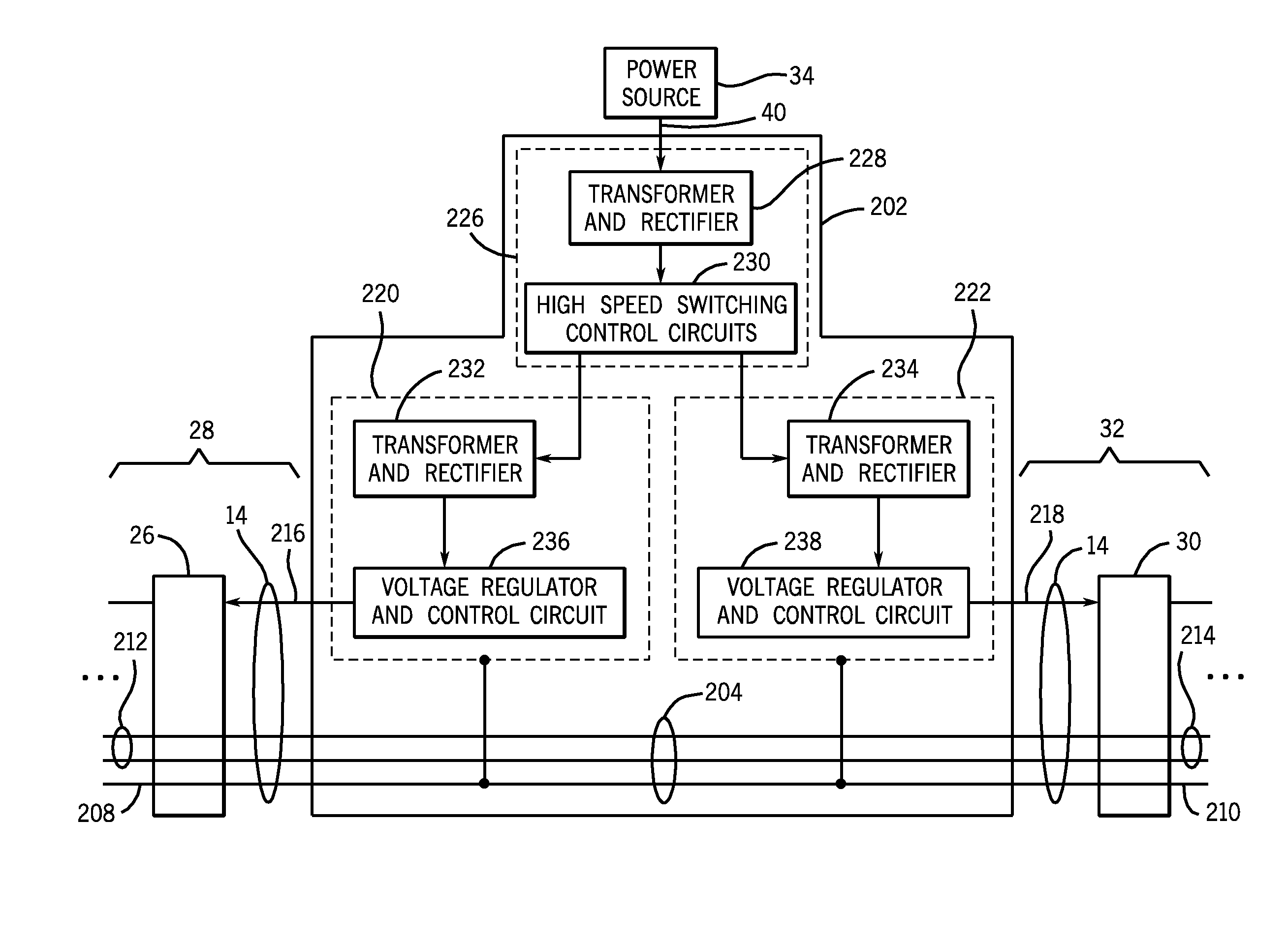
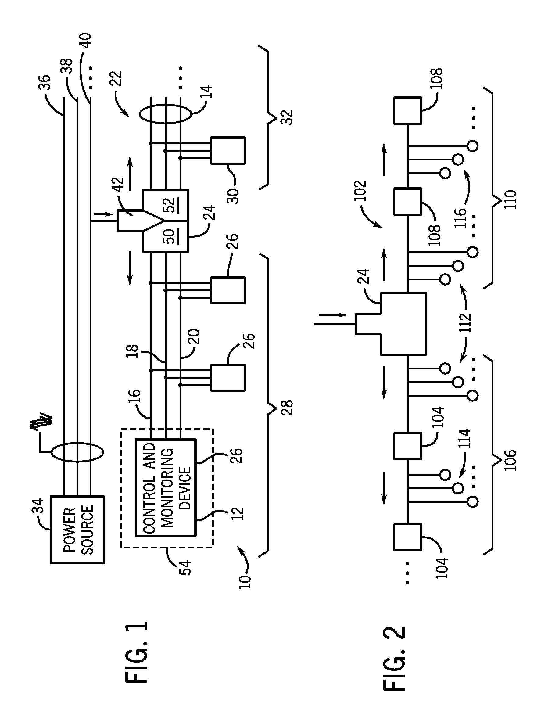
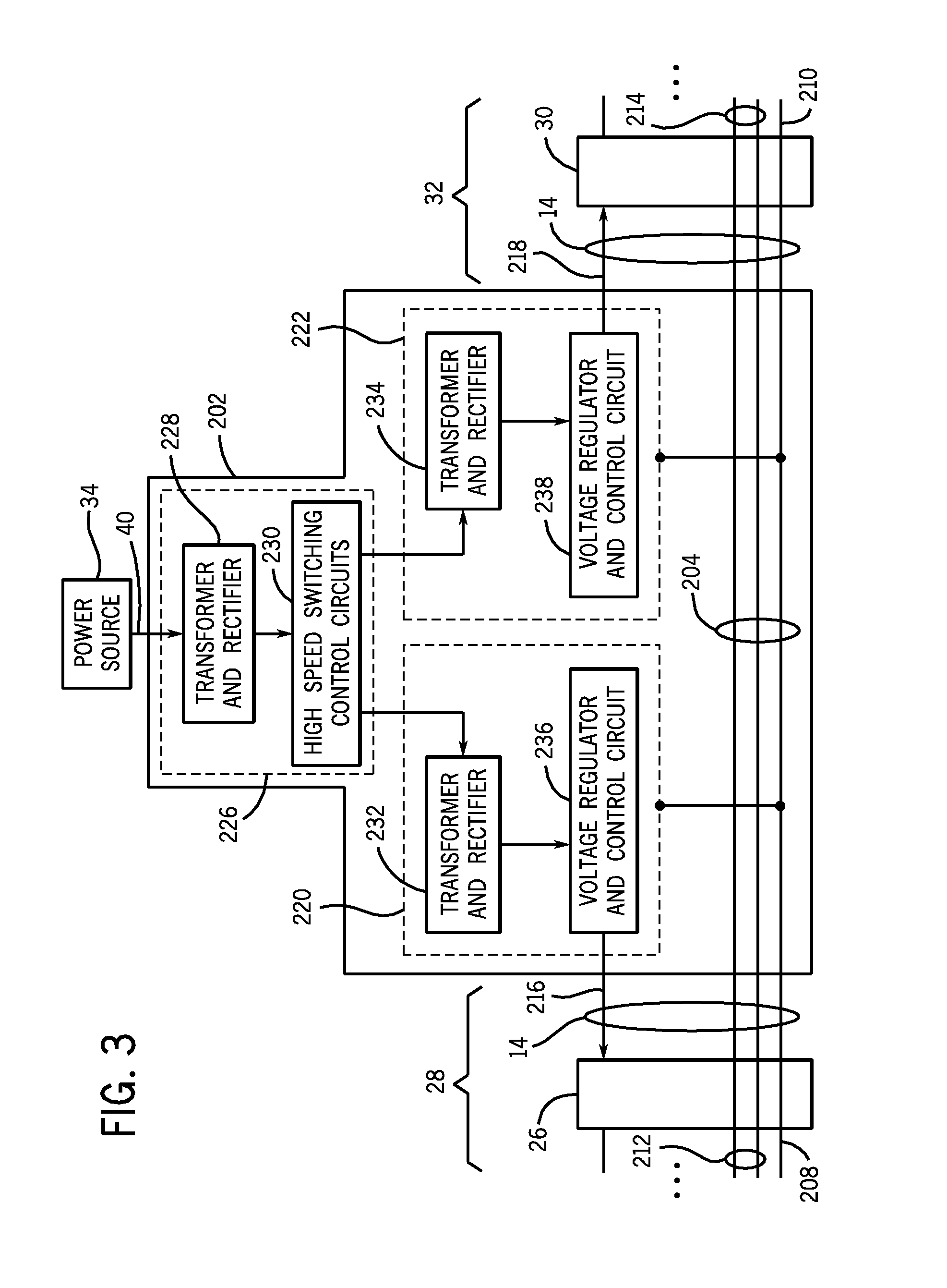
[0016]Turning now to the drawings, and referring first to FIG. 1, a control and monitoring system is illustrated and designated generally by reference numeral 10. The system 10 may be incorporated into any of a variety of industrial settings, which might include manufacturing processes, assembly lines, material handling and conveyers, chemical process controls, fluid handling systems, and so forth. The present techniques are not intended to be limited to any particular types of monitored or controlled processes.

[0017]As illustrated, the system 10 includes various components for supplying electrical power and signals to sensors, controllers, mechanical equipment, and the like that are communicatively coupled with and incorporated into the system 10. As will be appreciated by those skilled in the art, components operated or monitored by the system 10 may include any of a wide range of features that have powered loads and / or points at which certain sensed data is collected for control ...


PUM


Abstract

A control and monitoring system power supply is described that receives a single power input and distributes power to two distinct segments of a control and monitoring system network. The power supply includes a single power input configured to receive AC from a power source and at least partially convert the AC power to an operable voltage for a network device. Further, the power supply includes dual power output drivers that share power from the single power input and distribute the power to distinct network cable segments. Each of the dual power output drivers is separate and common grounded with respect to the other.

Description

CROSS REFERENCE TO RELATED APPLICATIONS[0001]This application is a Nonprovisional Patent Application of Provisional Patent Application No. 61 / 046,231, entitled “Single-Input and Dual-Output Power Supply with Integral Coupling Feature”, filed Apr. 18, 2008, which is herein incorporated by reference.BACKGROUND[0002]The present invention relates generally to control and monitoring networks, such as those used in industrial applications. More particularly, the invention is directed to techniques associated with powering and facilitating communication between multiple networked devices in a control and monitoring system.[0003]A control and monitoring system may include a device or set of devices that monitor and / or manage the behavior of other devices of a system. Indeed, a control and monitoring system may essentially act as a nerve center for a system. For example, in many industrial and commercial applications, a device, such as a programmable controller or computer, may send and rece...

Claims


Application Information

Patent Timeline
Patent Type & Authority Applications(United States)
IPC IPC(8): H02J3/00
CPCH02J1/00H02M2001/008H02J2001/002H02J1/002H02M1/008
Inventor FURUKAWA, JAMESGOEBEL, NICHOLAS R.STACHOWIAK, AMY L.HINDS, DERRICK S.
Owner ROCKWELL AUTOMATION TECH
Why Eureka
Try Eureka