Image pickup apparatus

a technology for removing equipment and images, applied in the field of image removing equipment, can solve problems such as user embarrassment, and achieve the effect of suppressing undesired changes

Active Publication Date: 2009-10-22
SONY CORP
View PDF6 Cites 22 Cited by
  • Summary
  • Abstract
  • Description
  • Claims
  • Application Information

AI Technical Summary

Benefits of technology

[0009]Thus, there is a need for an image pickup apparatus capable of suppressing un...

Problems solved by technology

In such a situation, because the subject distances of both the persons are close to each other, the selected AF area is often frequently changed due to, e.g., a measurement error of the distance measuring sensor.
However, the frequent changes of the selected AF area cause various...

Method used


Image

  • Image pickup apparatus
  • Image pickup apparatus
  • Image pickup apparatus

Examples


Embodiment Construction

[0032]An embodiment of the present invention will be described below with reference to the drawings.

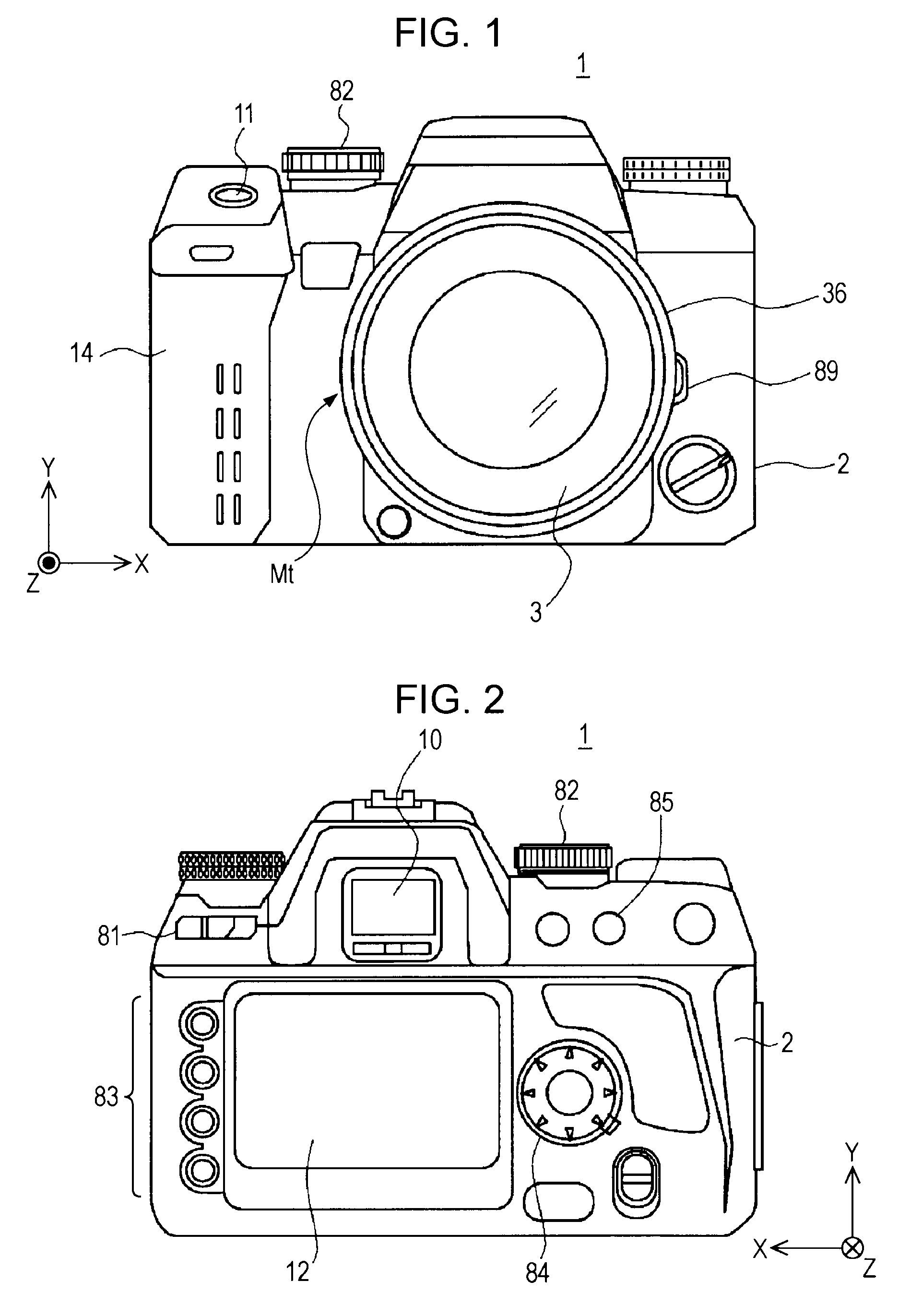
[0033]FIGS. 1 and 2 each illustrate an external appearance of an image pickup apparatus 1 according to the embodiment of the present invention. More specifically, FIG. 1 is a front external view of the image pickup apparatus 1, and FIG. 2 is a rear external view of the image pickup apparatus 1. The image pickup apparatus 1 is a single-lens reflex digital camera with an interchangeable lens.

[0034]As illustrated in FIG. 1, the image pickup apparatus 1 includes a camera main unit (camera body) 2. An interchangeable imaging lens unit (i.e., an interchangeable lens) 3 is detachably attached to the camera body 2.

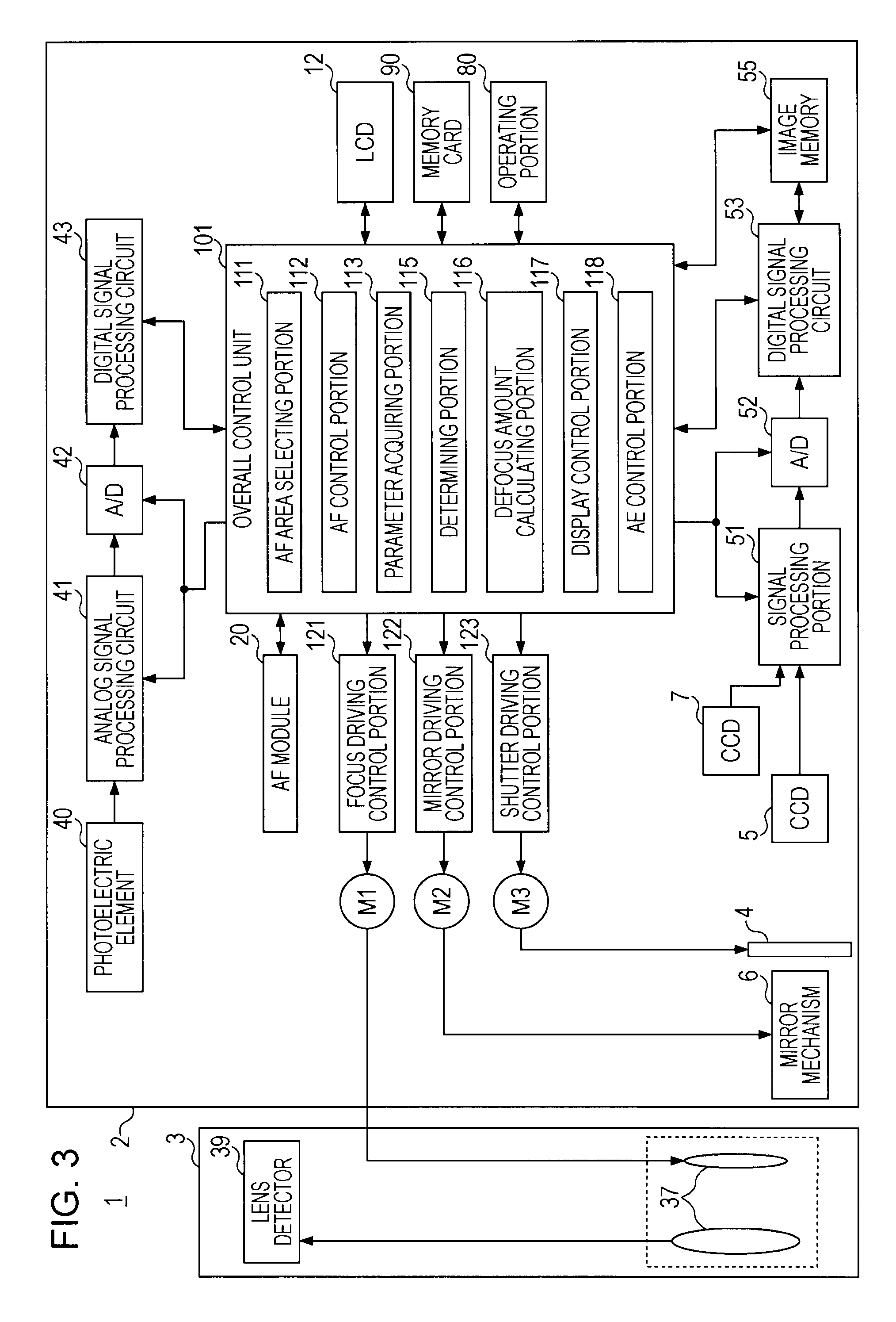
[0035]The imaging lens unit 3 includes, as main components, a barrel 36, lens groups 37 (see FIG. 3), and an aperture, the lens groups 37 and the aperture being disposed inside the barrel 36. The lens groups 37 (imaging optical system) include, e.g., a focus lens which is movable in...


PUM


Abstract

In an image pickup apparatus, a light receiving unit produces a first signal at a first timing and a second signal at a second timing later than the first timing. First and second parameters for detecting a scene change are acquired based on the first and second signals, respectively. The presence or the absence of a scene change is determined based on both the parameters. The apparatus further includes a selecting unit configured to select a focusing target AF area from among a plurality of AF areas, and a focusing control unit configured to execute focusing control by using focusing information with respect to the AF area selected by the selecting unit. When the determining unit determines that the scene change is not present, the selecting unit selects the AF area having been selected at the first timing, as the focusing target AF area, at the second timing continuously.

Description

BACKGROUND OF THE INVENTION[0001]1. Field of the Invention[0002]The present invention relates to an image pickup apparatus, such as a digital camera.[0003]2. Description of the Related Art[0004]In one of autofocusing (AF) techniques for image pickup apparatuses, a focusing target area is selected from among a plurality of AF areas in accordance with predetermined criteria, and a subject in the selected AF area is brought into an in-focus state (see, e.g., Japanese Unexamined Patent Application Publication No. 2007-171298).SUMMARY OF THE INVENTION[0005]When distances to respective subjects in the plurality of AF areas (i.e., subject distances) are close to one another, the selected AF area is often frequently changed depending on, e.g., measurement accuracy of a distance measuring sensor.[0006]It is here assumed, for example, that in performing AF control to bring the nearest (shortest-distance) subject (i.e., the subject closest to an image pickup apparatus) into an in-focus state (...

Claims


Application Information

Patent Timeline
IPC IPC(8): G03B13/24G03B13/36
CPCH04N5/23212H04N23/672H04N23/675H04N23/635
Inventor NAGAHATA, JUNKOSOGAWA, HISAMOKISHIMOTO, TSUYOSHIKATAYAMA, TOSHIO
Owner SONY CORP
Why Eureka
Try Eureka