Welding power output control method

A welding power supply and output control technology, applied in welding equipment, manufacturing tools, arc welding equipment, etc., can solve the problems of increasing the inductance value of welding power supply and unable to suppress the fluctuation state, so as to improve the fluctuation state, good welding quality, and stable The effect of welding state

Active Publication Date: 2006-05-03
DAIHEN CORP
View PDF1 Cites 22 Cited by
  • Summary
  • Abstract
  • Description
  • Claims
  • Application Information

AI Technical Summary

Problems solved by technology

Image 6 The current change shown at time t21 to t22 in (A) is also caused by disturbance, but since this figure shows the case of short-circuit arc welding with relatively small welding current value i and short arc length, the above-mentioned p

Method used


Image

  • Welding power output control method
  • Welding power output control method
  • Welding power output control method

Examples


no. 1 Embodiment approach

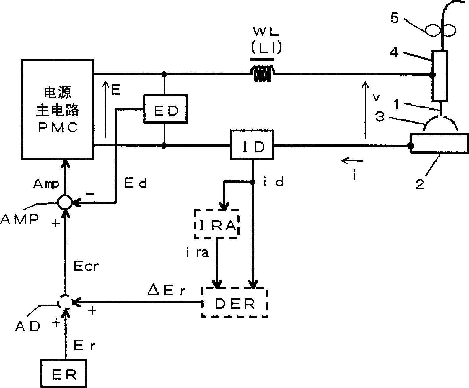
[0045] Embodiment 1 of the present invention performs a moving average on the welding current i, calculates the welding current moving average ira, and calculates the error amplification value ΔEr=Gain·(ira-i) between the welding current moving average ira and the welding current i The error amplification value ΔEr is added to the predetermined voltage setting value Er to calculate the voltage control setting value Ecr, and the output is controlled so that the voltage control setting value Ecr is approximately equal to the output voltage E of the welding power source. The above-mentioned gain (Gain) is a predetermined amplification factor. Hereinafter, it demonstrates in detail with reference to drawings.

[0046] figure 1 It is a block diagram of the welding power supply for implementing the output control method of the welding power supply according to the first embodiment. In this figure, with the above Figure 5 The same symbols are attached to the same blocks, and desc...

no. 2 Embodiment approach

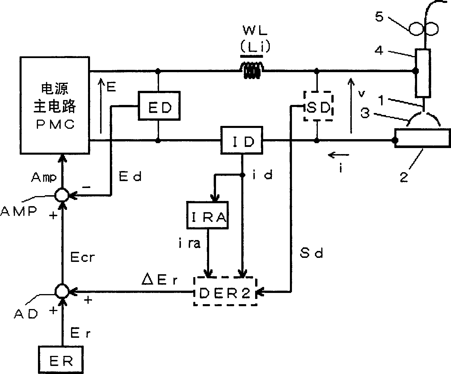
[0051] In Embodiment 2 of the present invention, in Embodiment 1, the voltage control setting value Ecr during the short-circuit period is set to a value equal to the voltage setting value Er, or to a value limited within a predetermined range by the voltage setting value Er. . As mentioned above, short circuits exceeding several ms rarely occur in globular transfer or spray transfer welding. During this short-circuit period, since the arc load changes to a short-circuit load, the welding current increases. At this time, if the present invention functions, an increase in welding current can be suppressed. However, during the welding period, increase the welding current, release the short circuit early, and stabilize the welding state on the arc regenerating side. Therefore, in Embodiment 2, the current change suppression control of the present invention is substantially prohibited during the short-circuit period. Hereinafter, it demonstrates in detail with reference to draw...


PUM


Abstract

In the present invention, the welding current (I) is detected, and the welding current detection value (id) is moving averaged to calculate the welding current moving average value (ira), and the welding current moving average value (ira) and the welding current detection value (id) are calculated. Between the error amplification value (ΔEr), the error amplification value (ΔEr) is added to the above-mentioned voltage setting value (Er) to calculate the voltage control setting value (Ecr), and the output is controlled so that the voltage control setting value (Ecr) is approximately equal to the above-mentioned output voltage (E). Therefore, in a welding power source used in globular transfer welding or spray transfer welding and in which the inductance value (Li) of the reactor (WL) is a large value of several hundred μH, the output is controlled so that the output voltage E of the welding power source and The output control method of the welding power source with the predetermined voltage setting value (Er) approximately equal can suppress the fluctuation of the welding current (i) due to the change of the wire feeding speed and the height of the welding gun.

Description

technical field [0001] The present invention relates to an output control method of a welding power source capable of obtaining good welding quality by suppressing fluctuations in welding current caused by disturbance in coarse drop transfer welding or spray transfer welding. Background technique [0002] In short-circuit arc welding in which short-circuit and arc are repeated between the wire and the base metal, it is important to ensure good welding quality by appropriately adjusting the change of welding current i during the short-circuit period and the arc period according to the fluctuation of the arc load. Since a welding power source with constant voltage characteristics is used in short-circuit arc welding, its output voltage is E[V], the total inductance of the internal and external reactors of the welding power source is L[H], and the total internal and external reactor inductance is L[H]. When the value of the external resistance is r [Ω], and the voltage of the a...

Claims


Application Information

Patent Timeline
IPC IPC(8): B23K9/10B23K9/095
Inventor 上园敏郎草野洁
Owner DAIHEN CORP
Why Eureka
Try Eureka