
Automated display quality measurement device

a display and measurement device technology, applied in measurement devices, instruments, scientific instruments, etc., can solve problems such as defective points in display devices, inconvenient use, and medical diagnosis errors

Inactive Publication Date: 2009-10-22
JOHN FLUKE MFG CO INC
View PDF5 Cites 40 Cited by
  • Summary
  • Abstract
  • Description
  • Claims
  • Application Information

AI Technical Summary

Benefits of technology

[0008]One aspect of the present invention is directed toward an apparatus and method of performing a quality assurance test on display devices for diagnostic imaging. In one aspect of the invention, the method of performing a quality assurance test on a display device comprises displaying a test pattern on the display device, moving the light meter over the test pattern and taking readings at designated locations, providing the readings to a software application, and comparing the readings to a set of ideal data stored in the software application.
[0009]In another aspect of the invention, a display device quality assurance testing system comprises at least one mount removeably secured to the display device, a bar moveably secured to the mount, the bar being substantially perpendicular to at least one mount. In addition, a light meter is mechanically...

Problems solved by technology

For example, the digital display device may have a particular defect that looks similar to a medical defect for a particular diagnostic image, thus resulting in an incorrect medical diagnosis.
Defects in the display devices may be caused by pressure damage, phosphor decay or other types of damage.
From the comparison, defective points in the display device may be detected.
The process of manually holding the light meter in front of the test pattern on the display device is laborious and time consuming.
It requires a person to manually hold the light meter in front of the monitor while the test is being conducted and to manually compare the test results with the expected results, therefore, lacking precision and accuracy.
Furthermore, manually holding the light meter may result in the light meter being held at multiple angles relative to the surface of the display device, rather than maintaining the light meter consistently parallel with the display device.
In addition, this process results in only a portion of the display device being tested.
Therefore, the results are not an accurate representation of the entire display device.

Method used


Image

  • Automated display quality measurement device
  • Automated display quality measurement device
  • Automated display quality measurement device

Examples


Embodiment Construction

[0016]Embodiments of the present invention are directed toward an apparatus and method of performing a quality assurance test on display devices for diagnostic imaging. Certain details are set forth below to provide a sufficient understanding of the embodiments of the invention. However, it will be clear to one skilled in the art that various embodiments of the invention may be practiced without these particular details.

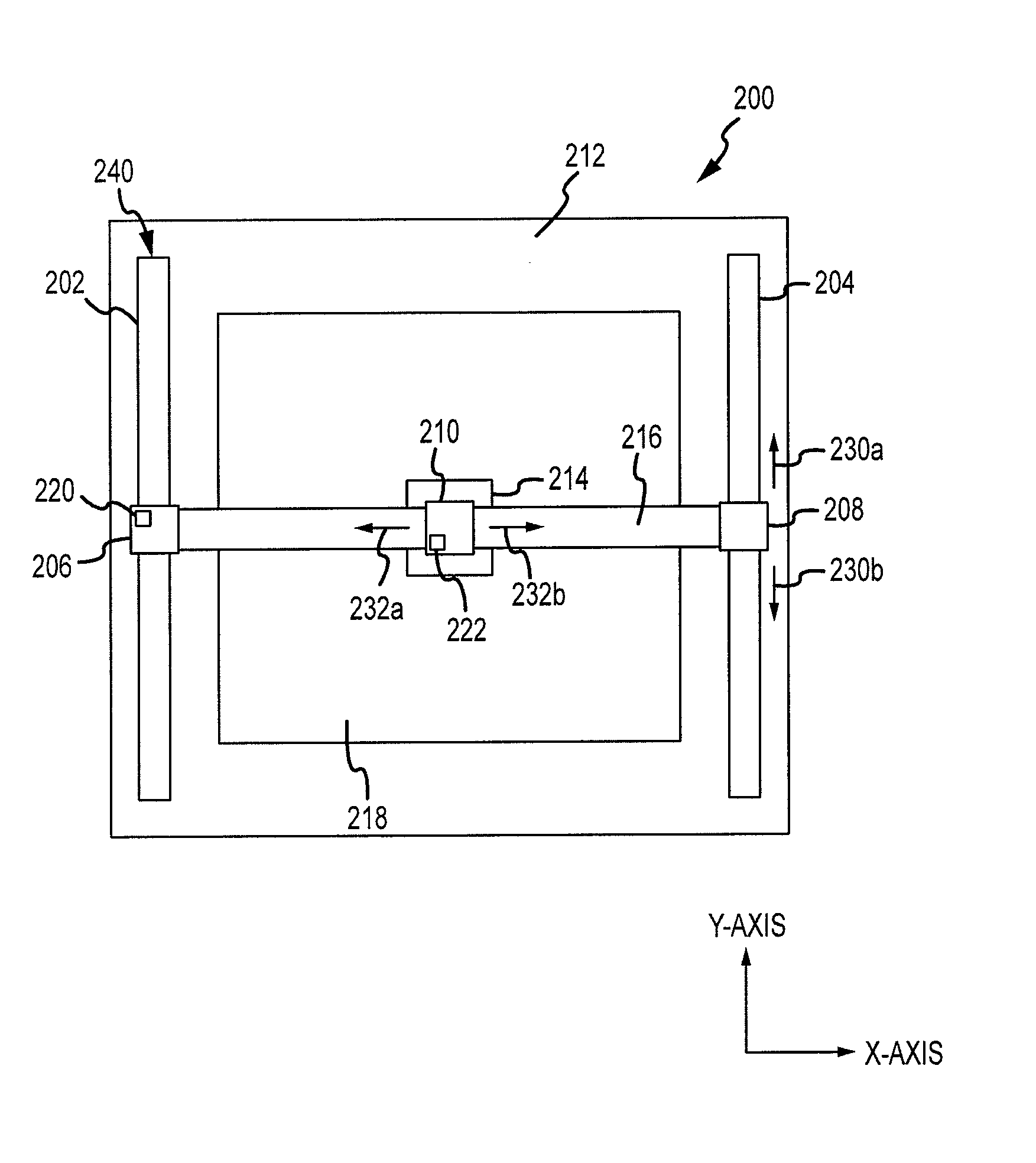
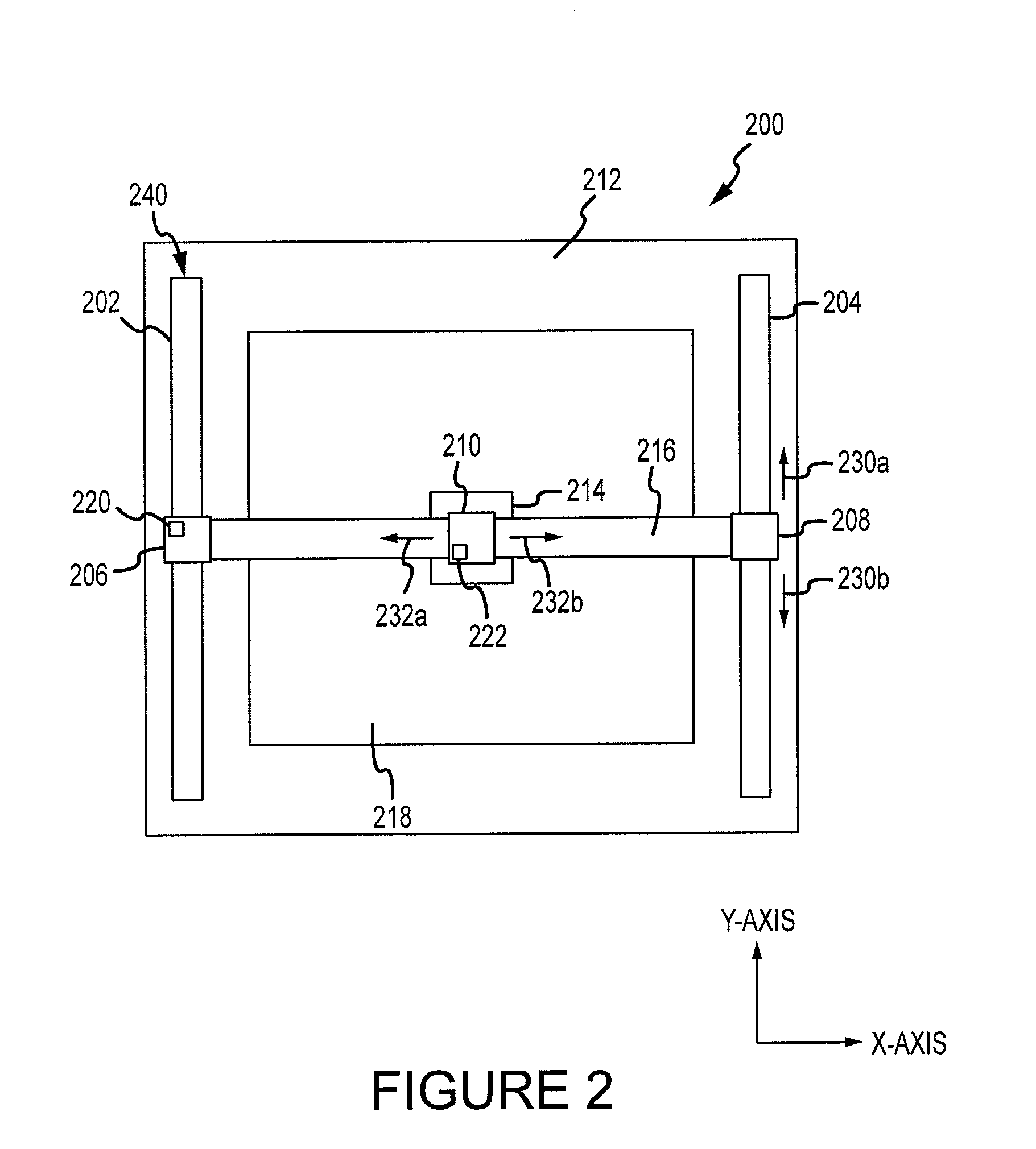
[0017]FIG. 2 is a block diagram of a mechanical system 240 for scanning a light meter 214 over a display device 200 according to one embodiment of the invention. The display device 200 includes a display frame 212 that surrounds a display screen 218, where the display screen 218 displays images. FIG. 2 shows two vertical mounts 202, 204 secured to opposites sides of the frame 212 of the display device 200. Two horizontal mounts, however, may also be used. For instance, one mount may be attached to the top of the display device 200 and the other attached to the bottom...


PUM


Abstract

A method and apparatus for automating a quality assurance test conducted on display devices used for diagnostic imaging. In one embodiment, the apparatus includes an automated mechanical system for scanning a light meter over a test pattern displayed on a display device. In another embodiment, the method comprises an automated method of comparing the measured data from the light meter with an ideal image. In another embodiment, the method comprises obtaining a digital image of the test pattern displayed on the display device, and the digital image is compared with an ideal image.

Description

TECHNICAL FIELD[0001]This invention is directed toward quality assurance testing for displays, and more particularly one or more embodiments of this invention relates to an automated quality assurance test for displays that provide medical diagnostic imaging.BACKGROUND OF THE INVENTION[0002]Diagnostic imaging provides a technique for displaying an image of the human body to medical professionals for diagnostic purposes. Diagnostic imaging includes images produced from X-ray, computerized tomography (CT), magnetic resonance imaging (MRI), ultrasound and the like. However, many other medical imaging techniques may be used for diagnostic imaging.[0003]Traditionally, photographic film was generally used for diagnostic imaging. Today, however, diagnostic images are often provided by a digital display device. As an example, digital display devices used in diagnostic imaging may include a cathode ray tube (CRT), Plasma monitors, liquid crystal display (LCD) and the like; however, other dis...

Claims


Application Information

Patent Timeline
IPC IPC(8): G01N21/17G06K9/00
CPCG01N21/95607G01N21/8806
Inventor KONOPA, KENNETH D.HEYDRON, PAUL
Owner JOHN FLUKE MFG CO INC
Learn More