Method and system for alignment of a pattern on a spatial coded slide image

a spatial coded slide image and pattern alignment technology, applied in the field of structured light stereoscopy, can solve the problems of not being able to correct after the projector, not being able to solve the problem of projector failure, and not being able to achieve good alignment along the epipolar line in the image of the camera

Active Publication Date: 2014-09-16
CREAFORM INC
View PDF8 Cites 13 Cited by
  • Summary
  • Abstract
  • Description
  • Claims
  • Application Information

AI Technical Summary

Benefits of technology

[0016]According to another broad aspect of the present invention, there is provided a method for facilitating matching of coded patterns between a projected image and a captured image in a system for 3D measurement of a shape of an object, having a projector and a camera in full-field structured light, comprising: calibrating the projector and the camera for intrinsic and extrinsic parameters; preparing a spatial coded slide image in which a pattern of the spatial coded slide image is aligned along epipolar lines; projecting the spatial coded pattern on a scene object using the projector; observing the spatial coded pattern on the object using the camera to generate a camera image; processing the camera image to match codes with the projected image;

Problems solved by technology

Some triangulation-based range sensors are generally adequate for close range measurements, such as inferior to a few meters.
The challenge in stereovision is to efficiently identify which pixels correspond to each other in each image.
However, the more complex the pattern will be, the greater the challenge will be to efficiently identify corresponding pixels and rays.
Unfortunately, there is an unresolved issue with the application of the principle of epipolar geometry.
Although it can be corrected after calibration through software calculation for the camera, it cannot be corrected afterwards for the projector.
In this case, a code initially aligned along a straight line (epipolar) in the projector image (hereafter referred to as slide image) will not be physically projected along a straight line after the lens and will thus not result in a good alignment along the epipolar line in the image of the camera.
For most lenses, distortion increases towards the side and corners of the images.
One will either lose these points, compensate with larger bands for encoding the signal along the distorted epipolar lines (thus reducing resolution of measurement) or apply more complex calculations that will take away the initial goal of simplifying matching.

Method used


Image

  • Method and system for alignment of a pattern on a spatial coded slide image
  • Method and system for alignment of a pattern on a spatial coded slide image
  • Method and system for alignment of a pattern on a spatial coded slide image

Examples


Embodiment Construction

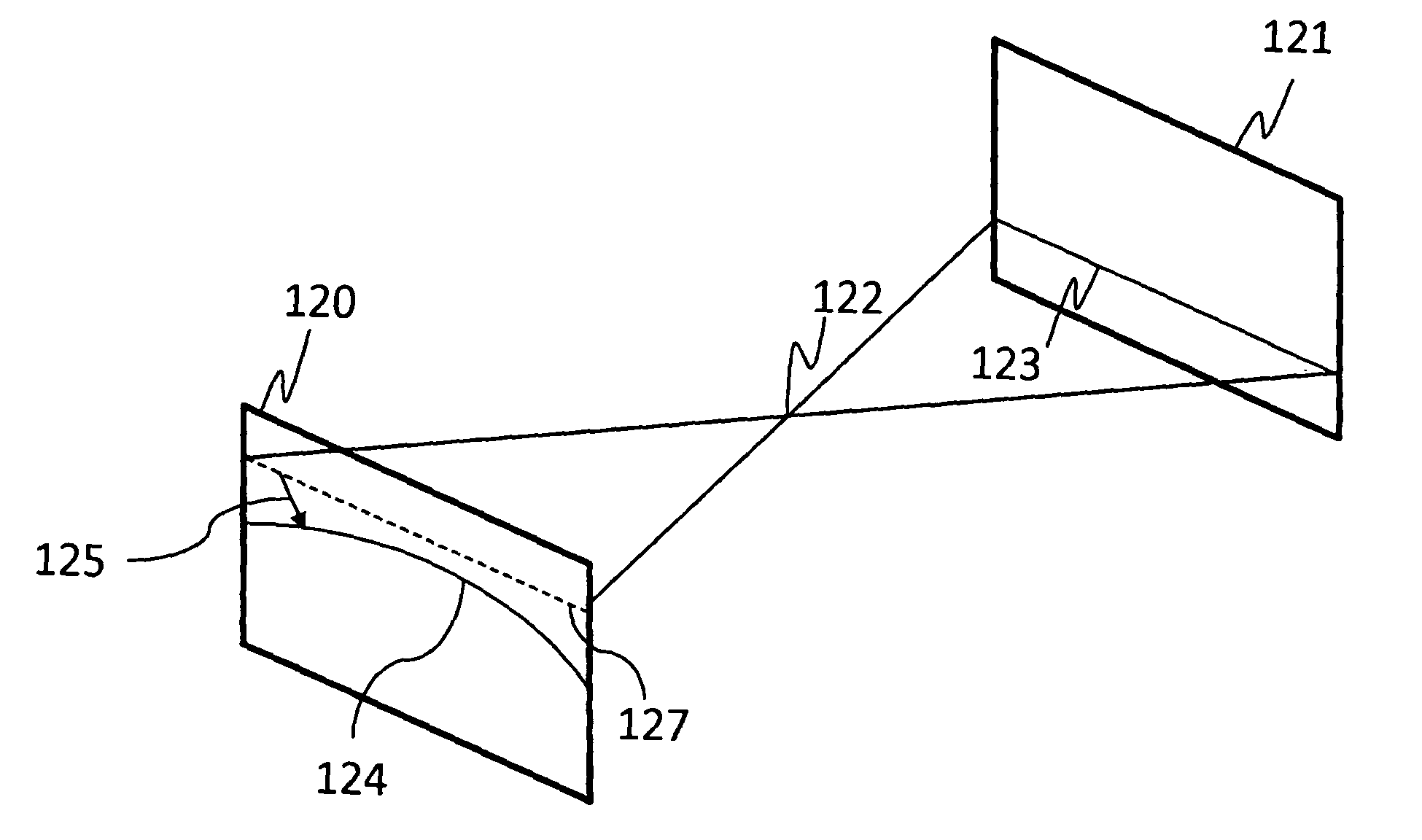
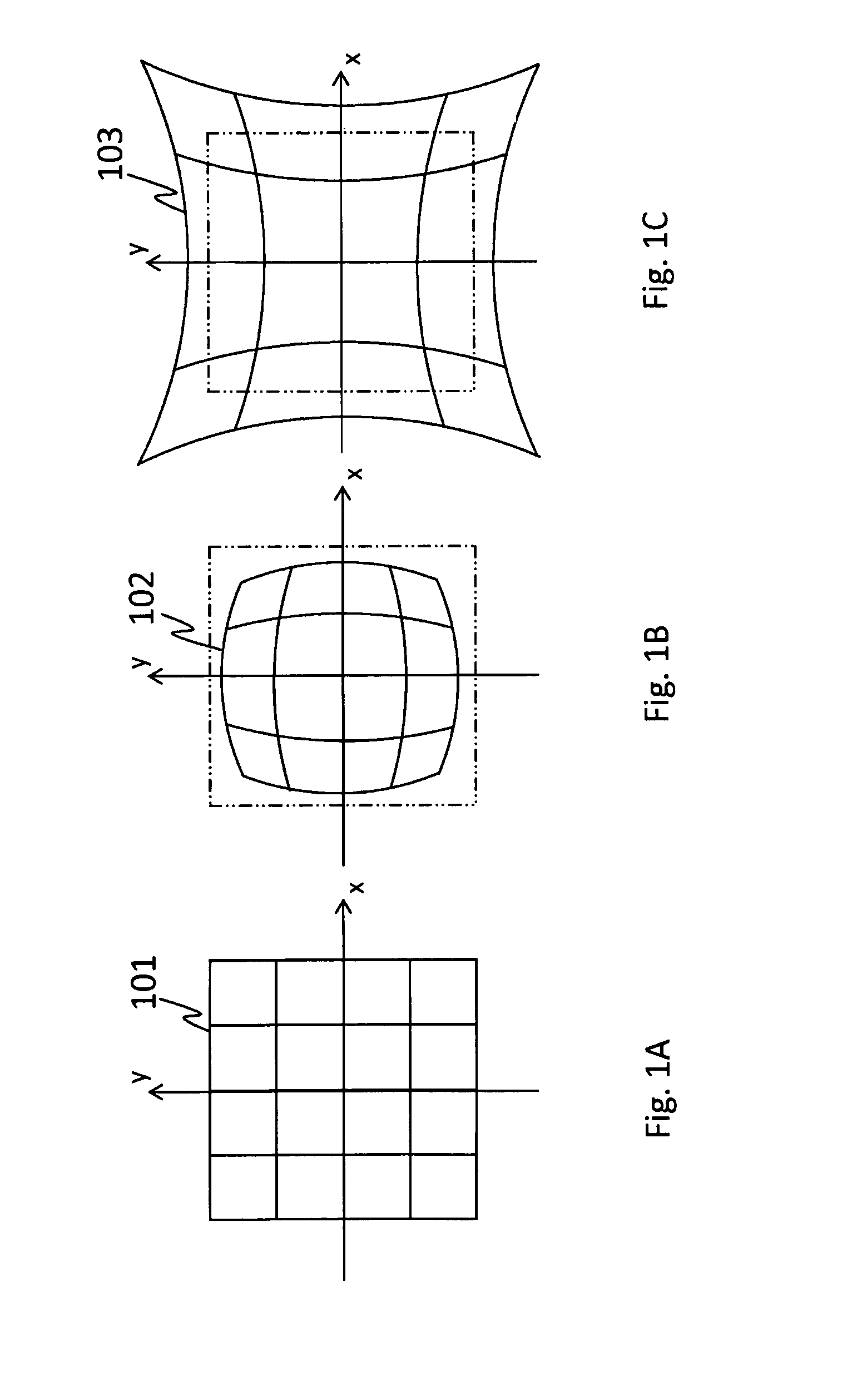
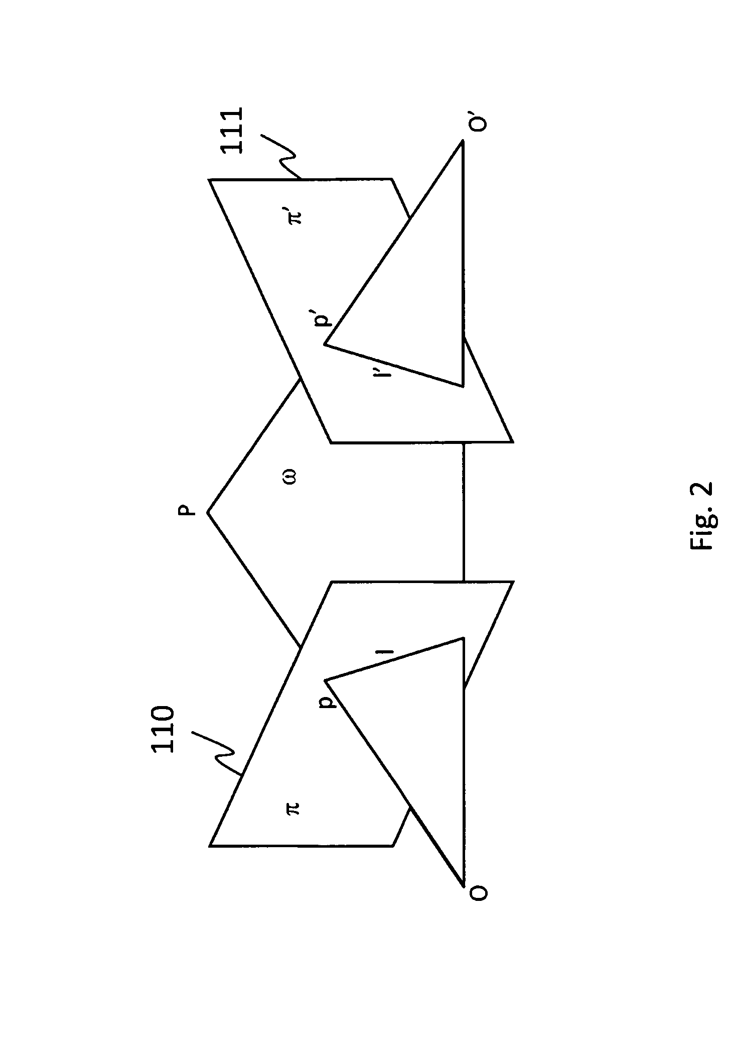
[0030]In order to find corresponding matches between the pattern projected by a projector and the pattern detected in the image captured by the camera, the present invention allows aligning higher resolution code, even near the sides and corners of the image. The projector lens will distort the image built on the projector slide. The slide is the physical imager component that is located before the optics of the projector. It is either a transmitting or reflecting imager component. The pattern codes aligned along ideal epipolar lines on the slide will thus result in curved lines instead of straight lines once projected through the lens. The method therefore aligns the pattern codes with the actual epipolar lines after the lens instead of aligning the pattern codes on the hypothetical non-distorted straight lines on the projector slide. The distortion induced by the lens optics of the projector is first modeled and the distortion model is then applied to deform the coded patterns ini...


PUM


Abstract

A method for preparing a spatial coded slide image in which a pattern of the spatial coded slide image is aligned along epipolar lines at an output of a projector in a system for 3D measurement, comprising: obtaining distortion vectors for projector coordinates, each vector representing a distortion from predicted coordinates caused by the projector; retrieving an ideal pattern image which is an ideal image of the spatial coded pattern aligned on ideal epipolar lines; creating a real slide image by, for each real pixel coordinates of the real slide image, retrieving a current distortion vector; removing distortion from the real pixel coordinates using the current distortion vector to obtain ideal pixel coordinates in the ideal pattern image; extracting a pixel value at the ideal pixel coordinates in the ideal pattern image; copying the pixel value at the real pixel coordinates in the real slide image.

Description

TECHNICAL FIELD[0001]The present invention generally relates to the field of three-dimensional scanning of the surface geometry of an object, and, more particularly, to structured light stereoscopy.BACKGROUND OF THE ART[0002]Three-dimensional scanning and digitization of the surface geometry of objects is commonly used in many industries and services, and their applications are numerous. A few examples of such applications are inspection and measurement of shape conformity in industrial production systems, digitization of clay models for industrial design and styling applications, reverse engineering of existing parts with complex geometry, interactive visualization of objects in multimedia, applications, three-dimensional documentation of artwork and artifacts, human body scanning for better orthotics adaptation, biometry or custom-fit clothing.[0003]The shape of an object is scanned and digitized using a ranging sensor that measures the distance between the sensor and a set of poi...

Claims


Application Information

Patent Timeline
Patent Type & Authority Patents(United States)
IPC IPC(8): H04N13/02H04N17/00
CPCH04N13/0275G01B11/2504G01B11/2513G06T5/006G06T7/0057G06T7/521H04N13/275
Inventor HEBERT, PATRICKROCHETTE, FELIX
Owner CREAFORM INC
Why Eureka
Try Eureka