Eureka AIR delivers breakthrough ideas for toughest innovation challenges, trusted by R&D personnel around the world.

Position mechanism

Inactive Publication Date: 2009-10-22
CHENG UEI PRECISION IND CO LTD
View PDF9 Cites 4 Cited by
  • Summary
  • Abstract
  • Description
  • Claims
  • Application Information

AI Technical Summary

Benefits of technology

[0007]As described above, after a product is shaped in the injection mold for one time, the product is semi-finished and named the semi-finished product. Then the semi-finished product is placed in the locating cavity of the locating body. The semi-finished product compresses the locating stopper to make the locating stopper move sideward. At the same time, the elastic force of the elastic component pushes the locating stopper to move toward the locating cavity. Then, the semi-finished product is firmly located in the locating cavity, which avoids the semi-finished product rotating or moving in the process of being shaped into the finished product. Therefore, the position precision of the position mechanism is raised, which ensures the shaping quality of the finished product.

Problems solved by technology

Because the plastic product is easily driven rotating or moving by external force in the process of being shaped, the conventional position mechanism cannot guarantee the position precision, that is, the shaping quality of the plastic product has no security.
If the plastic product is driven rotating or moving in the process of being shaped into the finished plastic product, the finished plastic product maybe has defects and is unserviceable and has to be discarded, which wastes material.

Method used


Image

  • Position mechanism
  • Position mechanism
  • Position mechanism

Examples


Embodiment Construction

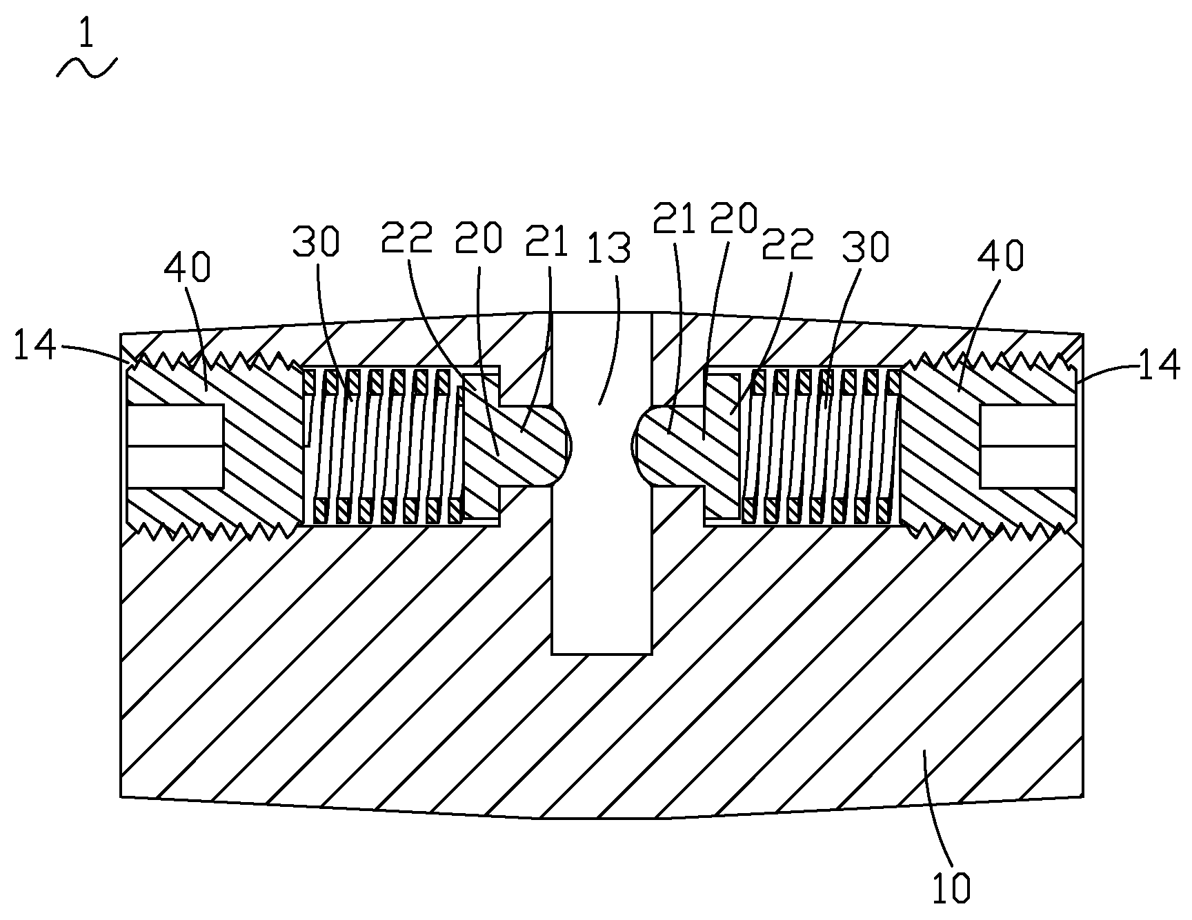
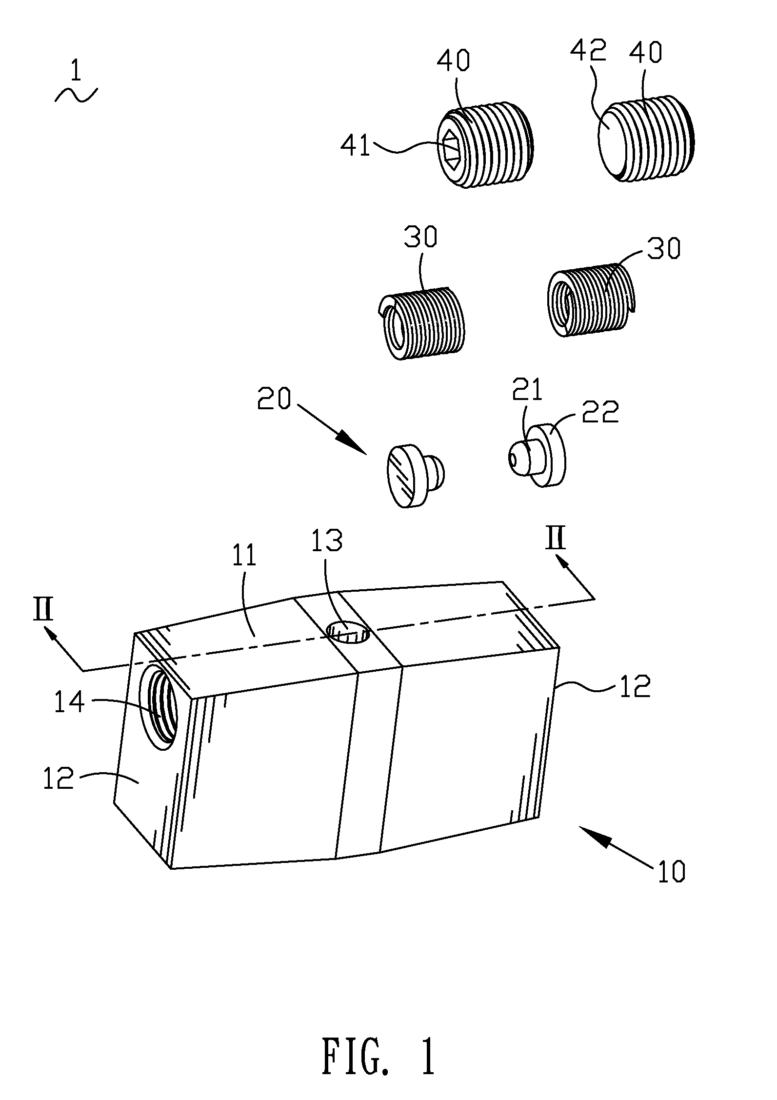
[0013]Referring to FIG. 1, a position mechanism 1 used in an injection mold is illustrated that includes a locating body 10, a pair of locating stoppers 20 received in the locating body 10, a pair of coil springs 30 received in the locating body 10 and blocked by the locating stoppers 20 and a pair of screws 40 mounted in the locating body 10 and jamming the coil springs 30.

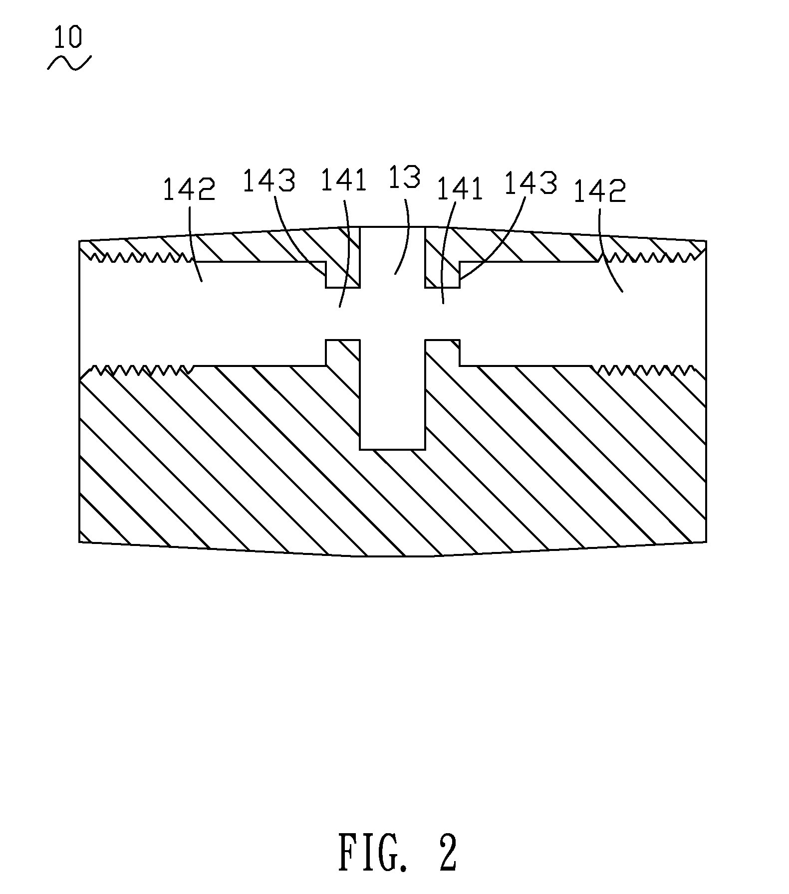
[0014]With reference to FIG. 1 and FIG. 2, the locating body 10, the locating stoppers 20, the coil springs 30 and the screws 40 are described in detail. The locating body 10 is substantially rectangular and has a top wall 11 and two sidewalls 12. A locating cavity 13 is defined at the center of the top wall 11 and extends into the inner of the locating body 10. Each of the two sidewalls 12 defines a receiving chamber 14 stretching into the inner of the locating body 10. The receiving chamber 14 has a limiting cavity 141 communicating with the locating cavity 13 and a retaining cavity 142 communicating with the l...


PUM

PropertyMeasurementUnit
Diameteraaaaaaaaaa
Elasticityaaaaaaaaaa

Abstract

The present invention provides a position mechanism including a locating body. The locating body defines a locating cavity and a receiving chamber communicating with the locating cavity. A locating stopper is received in the receiving chamber of the locating body with an end thereof toward the locating cavity, and an elastic component is received in the receiving chamber of the locating body and resiliently biases the locating stopper into the locating cavity.

Description

BACKGROUND OF THE INVENTION[0001]1. Field of the Invention[0002]The present invention relates to a position mechanism, and more particularly to a position mechanism used in an injection mold for positioning a semi-finished product to be shaped into a finished product in the injection mold.[0003]2. The Related Art[0004]The injection molding technology is widely used in the mold field for shaping a plastic product. Generally, different parts of the plastic product are made from different kinds of material, so that the plastic product needs to be positioned and shaped for several times. Supposing that the plastic product is made from two different kinds of material, the plastic product needs to be shaped for two times. Correspondingly, a mold where the plastic product is shaped includes a first injection molding apparatus and a second injection molding apparatus for shaping the plastic product. A part of the plastic product is shaped in the first injection molding apparatus of the mold...

Claims


Application Information

Patent Timeline
IPC IPC(8): B29C45/14
CPCB29C45/1615B29C45/14065
Inventor CHEN, CHIH-YUHUANG, JIAN-GUANGWU, CHUN-YANLIANG, GUO-NING
Owner CHENG UEI PRECISION IND CO LTD
Why Eureka
Eureka Blog
Learn More