Ultrasonic wave hair set apparatus

a hair set and ultrasonic wave technology, applied in the direction of mechanical vibration separation, curling-tongs, generators/motors, etc., can solve the problems of hair damage, ultrasonic wave hair set apparatus, and larger power consumption

Inactive Publication Date: 2009-10-29
MATSUSHITA ELECTRIC WORKS LTD
View PDF15 Cites 19 Cited by
  • Summary
  • Abstract
  • Description
  • Claims
  • Application Information

AI Technical Summary

Benefits of technology

[0006]An ultrasonic wave hair set apparatus in accordance with an aspect of the present invention comprises a main frame, an ultrasonic vibration generating means which is provided on the main frame and generates ultrasonic vibrations, and a burn injury prevention means that prevent a portion of a human body other than hairs from touching to the vibration face of the ultrasonic wave generating means.
[0007]By providing the burn injury prevention means, even if a user touches a portion of a human body other than hairs such as a finger to the ultrasonic vibration generating means of the ultrasonic wave hair set apparatus in long time, the ultrasonic vibration may not be transmitted to the portion of the human body, so that the finger may not be heated from within and the finger may not be burnt injury.

Problems solved by technology

The above mentioned heat-type hair set apparatus, however, has disadvantages that power consumption becomes larger, and it damages hairs because the heating face of a high temperature is pressed to the hairs.
If a portion of a human body other than hairs (typically, finger) touches the vibration face during vibrating by mistake, the ultrasonic wave hair set apparatus, however, has a disadvantage that the portion may be burned.
In contrast, when a finger touches the vibration face of the ultrasonic wave hair set apparatus, since the temperature of the vibration face is lower, the finger may rarely be taken off reflectively, and consequently, there is a possibility that the finger will be heated from within during touching the finger to the vibration face in a long time, and the finger may be burned.

Method used


Image

  • Ultrasonic wave hair set apparatus
  • Ultrasonic wave hair set apparatus
  • Ultrasonic wave hair set apparatus

Examples


first embodiment

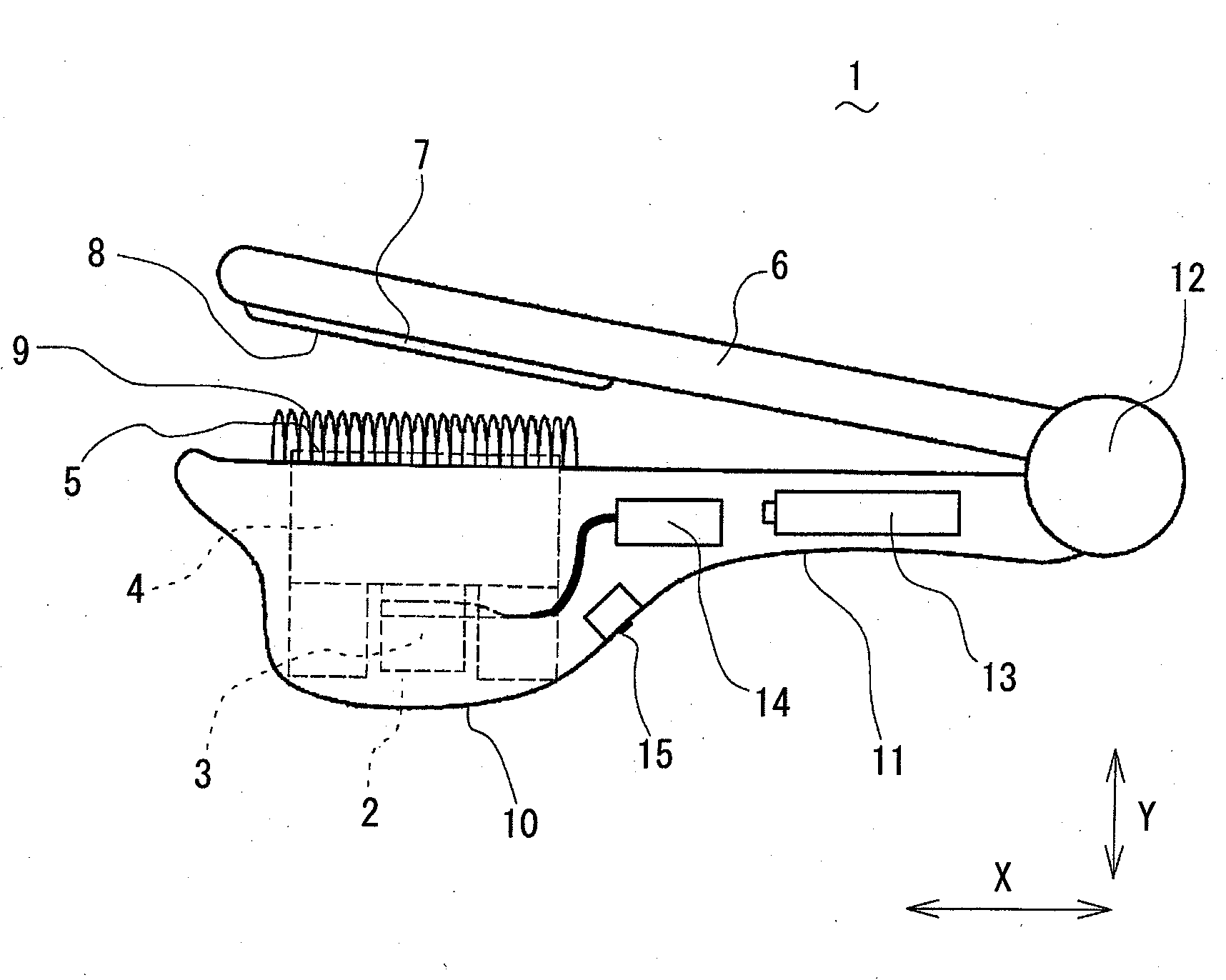
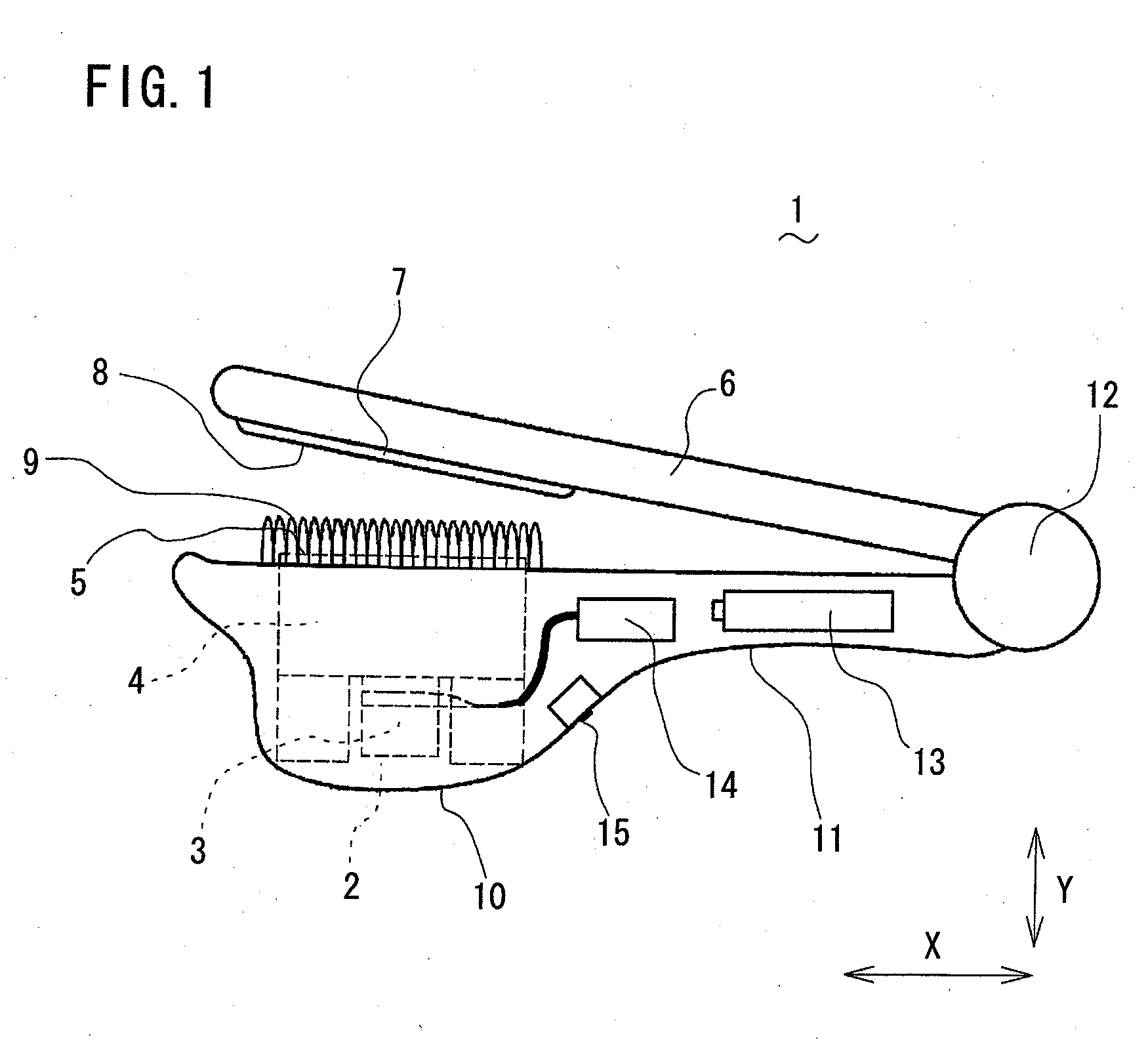
[0017]An ultrasonic wave hair set apparatus in accordance with a first embodiment of the present invention is described with reference to figures. As shown in FIG. 1, the ultrasonic wave hair set apparatus in accordance with a first embodiment is configured by a main frame 10 in which a portion near to a rear end thereof serves as a grip 11, an ultrasonic vibration block 2 which is provided in an inside of the main frame 10 near to a front end thereof, a battery 13 and a driving circuit 14 that drives the ultrasonic vibration block 2, an operation switch 15 that controls driving of the ultrasonic vibration block 2, a pinching lever 6 that is rotatably pivoted within a predetermined angle region by a hinge 12 at the rear end of the main frame 10, and a presser plate 7 provided at a position near to the front end of the main frame 10 and to face the ultrasonic vibration block 2, and so on. A front face of the presser plate 7 facing the main frame 10 serves as a pressing face. As for t...

second embodiment

[0025]Subsequently, an ultrasonic wave hair set apparatus in accordance with a second embodiment of the present invention is described with reference to FIGS. 6A and 6B. Elements which are the same as or similar to those in the above mentioned first embodiment are designated by the same numerals and the detailed descriptions of them are omitted.

[0026]As shown in FIGS. 6A and 6B, an ultrasonic vibration block 2 has a plurality of (three lines in the illustrated example) ultrasonic horns 4A to 4C which are arranged in parallel, and a plurality of vibration faces 5A to 5C on the surfaces of them. Furthermore, a plurality (four in the illustrated example) of comb shaped protection members 9A to 9D is provided along both sides of the vibration faces 5A to 5C in longitudinal directions of them. A plurality of grooves 71 is formed on a presser plate 7 provided at a portion near to a front end of a pinching lever 6 in a longitudinal direction of the presser plate 7 so as to avoid contacting...

third embodiment

[0030]Subsequently, an ultrasonic wave hair set apparatus in accordance with a third embodiment of the present invention is described with reference to FIGS. 7A to 7C. Elements which are the same as or similar to those in the above mentioned first embodiment are designated by the same numerals and the detailed descriptions of them are omitted.

[0031]In the third embodiment, a spacing detection sensor 20, which detects a distance “D” between a pressing face 8 of a presser plate 7 of a pinching lever 6 and a vibration face 5 of an ultrasonic horn 4 of a main frame 10 at front end portions of them, is comprised as a safety switch further to protection members 9. As shown in FIG. 7A, the spacing detection sensor 20 is configured by a push-on switch 21 provided on an opposing face 10a of the main frame 10 which faces the pinching lever 6, and a protrusion 22 provided on an opposing face of the pinching lever 6 which face the main frame 10. A protruding height of the protrusion 22 is selec...


PUM


Abstract

An ultrasonic wave hair set apparatus is configured by a main frame, an ultrasonic vibration block provided on the main frame, a pinching lever rotatably provided on the main frame, a presser plate provided on the pinching lever and having a pressing face. The ultrasonic vibration block is further comprised of an ultrasonic oscillator and an ultrasonic horn having a vibration face, and a comb shaped protection member is provided to enclose the vibration face. Even if a user penetrates a finger between the pinching lever and the main frame, the finger touches the protection member, so that it rarely touches the vibration face directly. Consequently, the ultrasonic vibrations are not transmitted to the finger, and burn injury can be prevented.

Description

TECHNICAL FIELD[0001]The present invention relates to an ultrasonic wave hair set apparatus which is used to set hairs by pressing hairs to a vibration face performing ultrasonic vibration.BACKGROUND ART[0002]For example, JPA 2000-333719 Official Gazette discloses a heat-type hair set apparatus that is used to set hairs. Such a heat-type hair set apparatus is provided a heating face heated by a heater on a main frame, and heats hairs by pressing the heating face to the hairs so as to set the hairs. The above mentioned heat-type hair set apparatus, however, has disadvantages that power consumption becomes larger, and it damages hairs because the heating face of a high temperature is pressed to the hairs.[0003]Thus, an ultrasonic wave hair set apparatus is proposed so that it comprises a vibration face performing ultrasonic vibration instead of the heating face, and vibrates hairs when the hairs are pressed to the vibration face so as to set hairs by heating hairs from within by ultra...

Claims


Application Information

Patent Timeline
Patent Type & Authority Applications(United States)
IPC IPC(8): A45D2/40B06B1/02
CPCA45D2200/207A45D1/18A45D1/04A45D1/08A45D2001/045
Inventor NUNOMURA, MAHITO
Owner MATSUSHITA ELECTRIC WORKS LTD
Why Eureka
Try Eureka