Vibration Reducing Bracket

a technology of vibration and bracket, applied in the direction of shock absorbers, machine supports, other domestic objects, etc., can solve the problems of poor achieve the effect of reducing vibration and nois

Inactive Publication Date: 2009-10-29
KOBE STEEL LTD
View PDF7 Cites 6 Cited by
  • Summary
  • Abstract
  • Description
  • Claims
  • Application Information

AI Technical Summary

Benefits of technology

[0003]In the case that the above vibration and noise are caused by resonance of the structures such as the bracket by which a vibrating apparatus is fixed, frame, exterior panel, and the like generated by exciting force of the vibrating apparatus such as a motor and the like, it is possible to reduce the vibration and noise by installing a dynamic vibration absorber using a viscoelastic material as described above (meaning a dynamic vibration absorber with vibration damping) whose resonance frequency is tuned to the resonance frequency of the above structures. However, in such a case that the vibration and noise are caused by forced excitation due to the vibration of the vibrating apparatus, even if the resonance frequency of a dynamic vibration absorber is tuned to the excitation frequency, the phase lag between the displacement and the force arising in the viscoelastic material occurs; therefore, the force produced from the dynamic vibration absorber does not become an opposite phase to the excitation force and the displacement of the point at which the dynamic vibration absorber is installed does not become zero, so the effect of reducing vibration and noise becomes poor.

Problems solved by technology

However, in such a case that the vibration and noise are caused by forced excitation due to the vibration of the vibrating apparatus, even if the resonance frequency of a dynamic vibration absorber is tuned to the excitation frequency, the phase lag between the displacement and the force arising in the viscoelastic material occurs; therefore, the force produced from the dynamic vibration absorber does not become an opposite phase to the excitation force and the displacement of the point at which the dynamic vibration absorber is installed does not become zero, so the effect of reducing vibration and noise becomes poor.

Method used


Image

  • Vibration Reducing Bracket
  • Vibration Reducing Bracket
  • Vibration Reducing Bracket

Examples


first embodiment

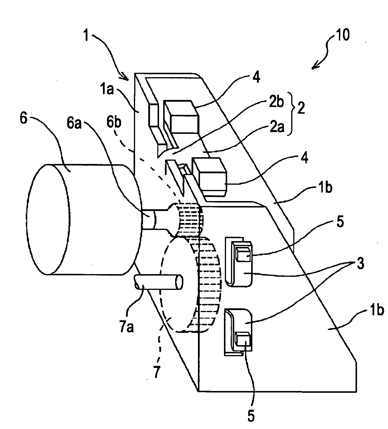
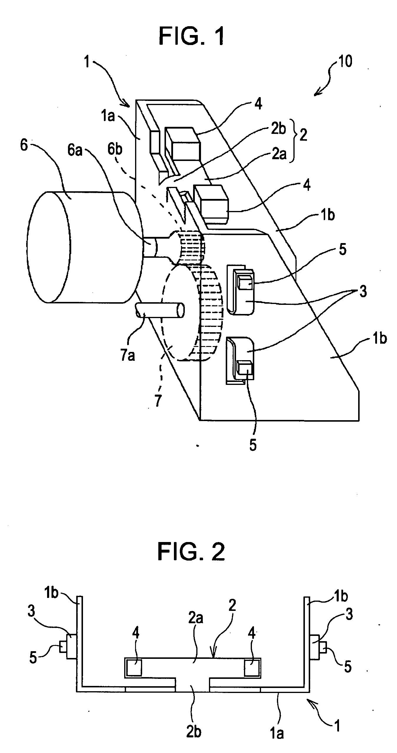
[0023]A vibration reducing bracket 10 (hereinafter called “bracket”) according to this embodiment is preferably used for fixing, for example, a rotation motor6 (vibrating apparatus) and a gear 7 that are used for OA (Office Automation) apparatuses, AV (Audio Visual) apparatuses or the like. The rotation motor 6 has a rotating shaft 6a and a gear 6b disposed at the tip of the rotating shaft 6a. And, the gear 7 is provided so as to mesh with the gear 6b of the rotation motor 6, and transfers the driving power of the rotation motor 6 to the other apparatuses (not shown) by rotating in accordance with rotation of the gear 6b.

[0024]The bracket 10 comprises, for example, a sheet of steel plate (bracket forming member), and includes a frame body (main body of the bracket) 1 and dynamic vibration absorbers (vibration absorbing portion) 2 and 3. The frame body 1 is formed by bending the steel plate in an angular U-shape as shown in FIG. 1 and FIG. 2, and has a substantially rectangular-shap...

second embodiment

[0050]Next, a second embodiment of the present invention will now be described. The dynamic vibration absorbers 2 and 3 of a vibration reducing bracket 10 of the first embodiment are formed by making slits in the frame body 1 and by bending the slit portion in an upward direction; being different from that, the dynamic vibration absorbers of a vibration reducing bracket 30 of this embodiment are formed by making slits in a frame body 20 as shown in FIG. 5. It is noted that a rotation motor 6 and the like to be installed on the rear face 20a are omitted from the drawing in FIG. 5.

[0051]The frame body 20 is formed by bending a steel plate so as to have a rear face 20a, and a side face 20b and top face 20c respectively perpendicular to the rear face 20a. On the rear face 20a, there are provided dynamic vibration absorbers 21 and 21 serving for reducing vibration arising in a direction perpendicular to the rear face 20a. That is, the dynamic vibration absorbers 21 are formed in a manner...

example modified

from this Embodiment

[0059]It is noted that although the dynamic vibration absorbers 24 and 24 of this embodiment respectively have three vibrating portions, the number of the vibrating portion is not limited to this but may be two, three or more than three. It may be altered as appropriate depending on vibration arising. It is also noted that each dynamic vibration absorber may be provided with a weight at the vibrating portion thereof. Moreover, the number of the dynamic vibration absorber may be one or more, and two dynamic vibration absorbers may not necessarily be provided in line symmetric.

[0060]The present invention is described in the above preferable embodiments, but the present invention is not limited to these examples. It is understood that various other embodiments are possible within the scope and split of the present invention. Furthermore, although the function and effect obtained by constitution of the invention are described in the present embodiments, these functio...


PUM


Abstract

Problem: To reduce vibration and noise of a bracket and the like, and also to save a work for manufacturing and shorten manufacturing time, in the case that a forced-excitation of a vibrating apparatus is a cause.
Solution: There are provided a frame body 1, to which a rotation motor 6 is fixed, and dynamic vibration absorbers 2, 3 which are structured in a manner such that slits are made in a portion of the frame body 1 and the slit part is bent in an upward direction, and is configured so that the vibrating portions 2a, 3a of the dynamic vibration absorbers 2, 3 vibrate in the vibrating direction of the frame body 1 being vibrated by the rotation motor 6.

Description

TECHNICAL FIELD[0001]The present invention relates to a vibration reducing bracket that reduces vibration of a bracket for fixing vibrating apparatus and reduces noise and the like.BACKGROUND ART[0002]High-speed rotating parts such as a motor, gear, HDD (Hard Disk Drive), and the like are used for Audio Visual (AV) and office Automation (OA) apparatuses such as a DVD (Digital Versatile Disc), printer, and the like. In recent years, greater functionality and speeding up of AV and OA apparatuses have been realized by increasing the rotational speed of these motors and gears; however, increasing vibration caused by such a situation brings about a change for the worse in reading accuracy of a DVD and / or an increase of noise arisen from the apparatus. For that reason, it is desired to reduce vibration and noise generated by a high-speed rotating motor or the like. As a dynamic vibration absorber for reducing such vibration, there is a product that a weight and viscoelastic material are f...

Claims


Application Information

Patent Timeline
Patent Type & Authority Applications(United States)
IPC IPC(8): F16F15/02
CPCF16F2230/36F16F7/104F16F15/02F16F15/00
Inventor SUGIMOTO, AKIOYAMAGUCHI, ZENZO
Owner KOBE STEEL LTD
Why Eureka
Try Eureka