Method for encapsulating permanent magnets of a rotor of a generator and rotor of a generator

a technology of permanent magnets and rotors, which is applied in the direction of electric generator control, magnetic circuit rotating parts, magnetic circuit shape/form/construction, etc., can solve the problems of weakening the bond between rotors and magnets, serious damage to generators, and complicated means for retaining magnets in rotors, etc., to achieve the effect of facilitating resin infusion

Inactive Publication Date: 2009-10-29
SIEMENS AG
View PDF5 Cites 27 Cited by
  • Summary
  • Abstract
  • Description
  • Claims
  • Application Information

AI Technical Summary

Benefits of technology

[0023]Generally, vacuum may be applied to the air tight enclosure between the membrane and the rotor yoke by means of vacuum ports. Furthermore, the resin can be infused into the air tight enclosure under vacuum. The resin may, for example, be infused into the air tight enclosure such that all cavities become filled with resin. Advantageously, a port which is located at the opposite end to a vacuum port is used for infusing resin. This facilitates the infusion of resin into the air tight enclosure under vacuum conditions.
[0024]The inventive method is very simple compared to what is described in the cited state of the art. No other means for retaining the magnets are necessary. The encapsulation generally serves a dual purpose. It protects the magnets from environmental influences, for example the humidity of the air, which could cause corrosions. Moreover, it helps retain the magnets in their position. Permanent magnets can be brittle, and the encapsulation prevents chips from becoming detached from the magnets. The encapsulation is manufactured using Vacuum Assisted Resin Transfer Moulding so that all cavities in the structure can be filled with resin, and so that all components of the rotor can become firmly bonded to each other.

Problems solved by technology

Such temperature increases can weaken the bond between the rotor and the magnets.
Unless measures are taken to keep the magnets in place, they might become detached from the rotor which could lead to serious damage to the generator.
The described rotor is provided with rather complicated means for retaining the magnets besides the resin.

Method used


Image

  • Method for encapsulating permanent magnets of a rotor of a generator and rotor of a generator
  • Method for encapsulating permanent magnets of a rotor of a generator and rotor of a generator
  • Method for encapsulating permanent magnets of a rotor of a generator and rotor of a generator

Examples


Embodiment Construction

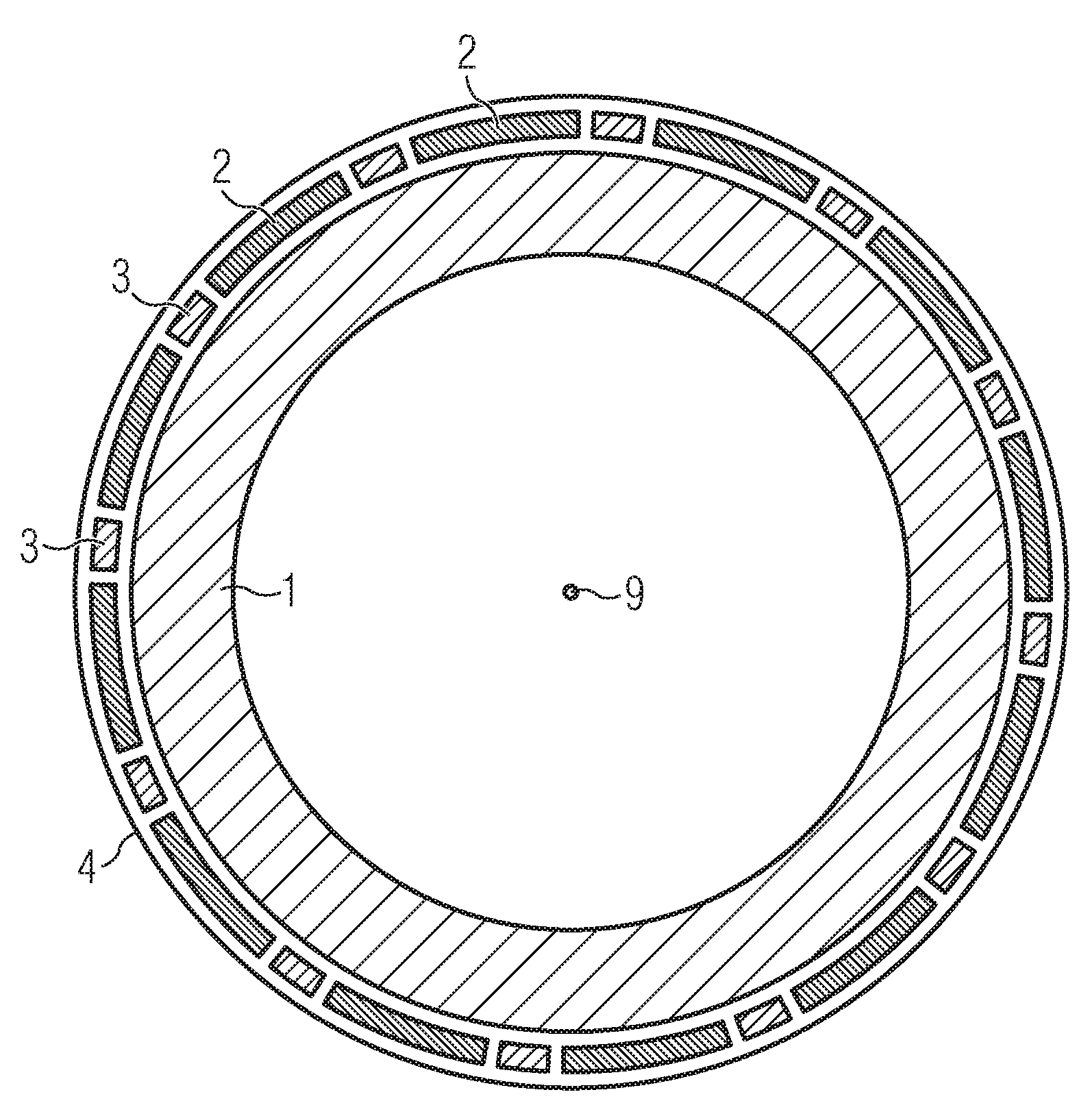
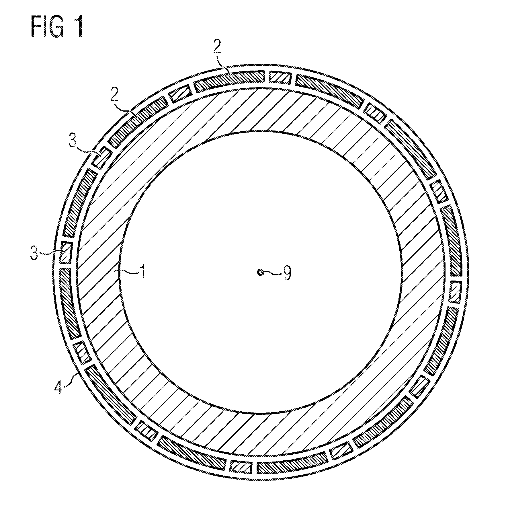
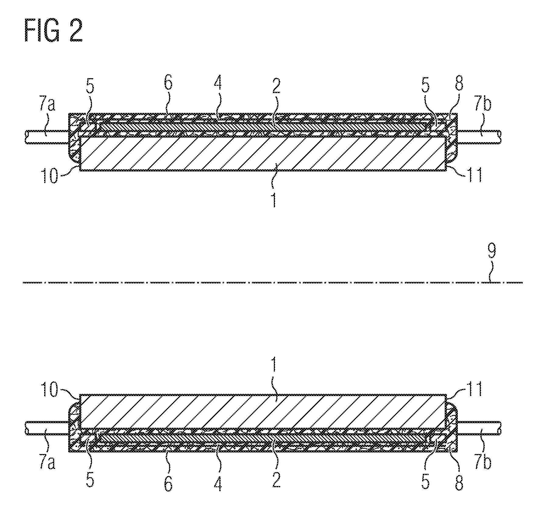
[0032]An embodiment of the present invention will now be described with reference to FIGS. 1 and 2. FIG. 1 schematically shows an inventive rotor of a generator in a sectional view perpendicular to the rotation axis 9. The inventive rotor comprises a rotor yoke 1, permanent magnets 2, spacers 3, and a thin sheet of non-magnetic material 4. Some details, like the rotor shaft and spokes, have been omitted in FIG. 1 and FIG. 2.

[0033]The rotor yoke 1 has a cylindrical shape. The permanent magnets 2 are placed on the outside of the rotor yoke 1. The spacers 3, which are made of a non-magnetic material, are placed between the magnets 2 such that the magnets 2 are maintained at regular angular distances.

[0034]During the assembly the magnets 2 are fixed in their positions by the magnetic forces and the spacers 3 are pressed into the openings between the magnets 2. Alternatively, a fast curing adhesive can be used to affix the magnets 2 and / or the spacers 3. A thin sheet 4 of non-magnetic ma...


PUM

PropertyMeasurementUnit
lengthaaaaaaaaaa
magnetic forcesaaaaaaaaaa
circumferenceaaaaaaaaaa

Abstract

A method is provided for encapsulating permanent magnets of a rotor of a generator. Magnets, which are shorter than a rotor yoke in an axial direction, are placed outside of the yoke leaving a short portion of the yoke free at both ends. Spacers of a non-magnetic material are placed between the magnets. End barriers are placed on the free portions of the yoke. A thin sheet of a non-magnetic material is folded around the magnets and the spacers, covering the entire length of the rotor, including the barriers. An air tight membrane is placed on the outside of the sheet and sealed to the ends of the yoke so that the membrane and the yoke together form an air tight enclosure. A vacuum is applied to the air tight enclosure between the membrane and the yoke. Resin is infused into the air tight enclosure and set.

Description

CROSS REFERENCE TO RELATED APPLICATIONS[0001]This application claims priority of European Patent Office application No. 08008189.6 EP filed Apr. 29, 2008, which is incorporated by reference herein in its entirety.FIELD OF INVENTION[0002]The present invention relates to a method for encapsulating permanent magnets of a rotor of a generator. It further relates to a rotor of a generator and to a wind turbine.BACKGROUND OF INVENTION[0003]In a permanent magnet generator the magnets are typically bonded, for example glued, to the rotor core. Under normal operation conditions significant temperature increases in a generator are possible. Such temperature increases can weaken the bond between the rotor and the magnets. Unless measures are taken to keep the magnets in place, they might become detached from the rotor which could lead to serious damage to the generator.[0004]In the document EP 1 367 700 A2 a method for manufacturing an encapsulated rotor of a permanent magnet motor is describe...

Claims


Application Information

Patent Timeline
Patent Type & Authority Applications(United States)
IPC IPC(8): H02K1/28H02K15/03F03D9/00
CPCB29C70/70B29K2105/203B29L2031/749Y10T29/49012H02K15/03H02K15/12Y02E10/725H02K1/278Y02E10/72
Inventor STIESDAL, HENRIK
Owner SIEMENS AG
Why Eureka
Try Eureka