Temporary power distribution panel

Active Publication Date: 2009-10-29
LBR TECH LLC
View PDF15 Cites 21 Cited by
  • Summary
  • Abstract
  • Description
  • Claims
  • Application Information

AI Technical Summary

Benefits of technology

[0019]Power distribution panels according to the present invention have the advantages of being readily deployed on walls, on studs, on posts, or even upon the ground. Such power distribution panels provide a convenient

Problems solved by technology

But prior to the completion of the buildings' electric wiring and/or prior to the establishment of regular electric service, providing electric power to t

Method used


Image

  • Temporary power distribution panel
  • Temporary power distribution panel
  • Temporary power distribution panel

Examples


Embodiment Construction

[0030]The present invention may be understood more readily by reference to the following detailed description of the invention taken in connection with the accompanying drawing figures, which form a part of this disclosure. It is to be understood that this invention is not limited to the specific devices, methods, conditions or parameters described and / or shown herein, and that the terminology used herein is for the purpose of describing particular embodiments by way of example only and is not intended to be limiting of the claimed invention. Any and all patents and other publications identified in this specification are incorporated by reference as though fully set forth herein.

[0031]Also, as used in the specification including the appended claims, the singular forms “a,”“an,” and “the” include the plural, and reference to a particular numerical value includes at least that particular value, unless the context clearly dictates otherwise. Ranges may be expressed herein as from “abou...


PUM


Abstract

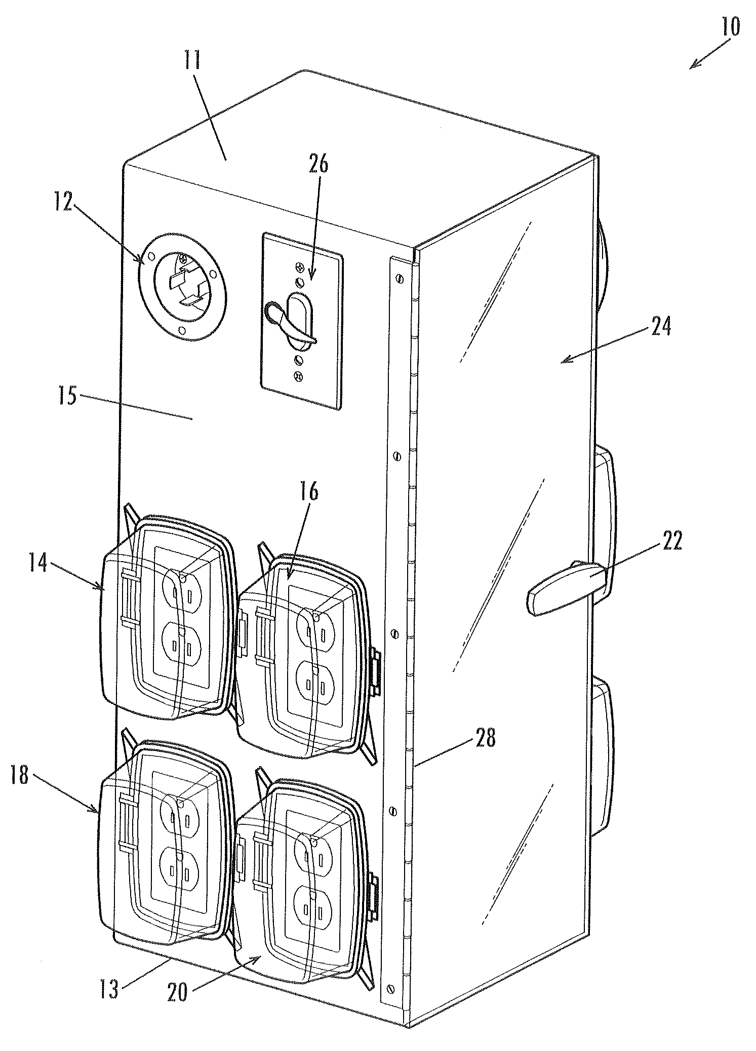
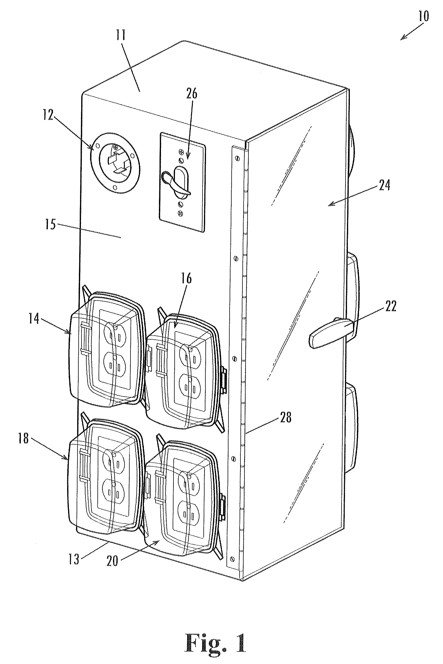
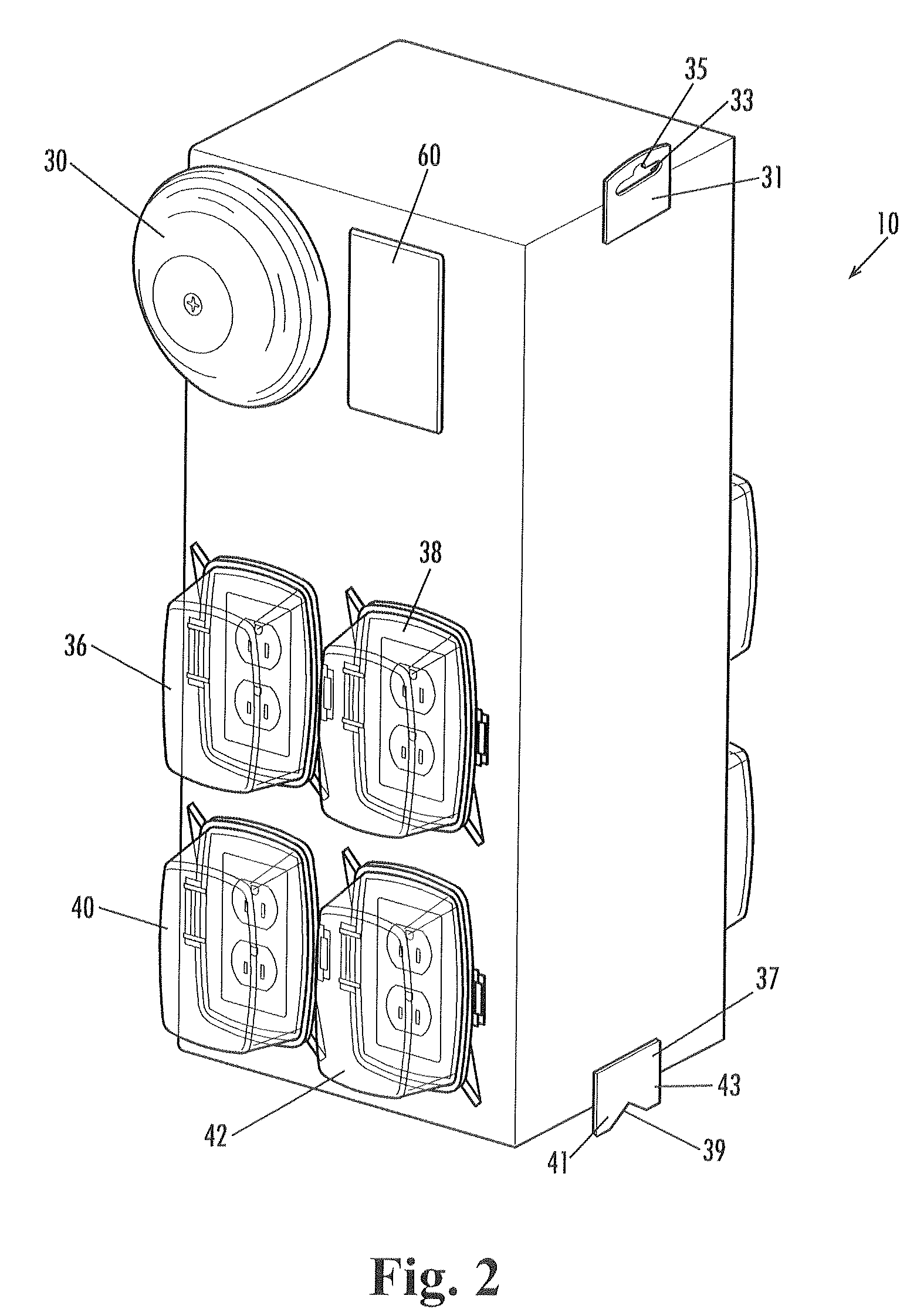
A temporary power distribution panel for use at a construction site comprises a box-like cabinet with an interior, an exterior, and a rear side having upper and lower hangers positioned on the rear side of the cabinet for securing the cabinet to a post, wall, or wall stud. The panel further comprises an electric power inlet for electrically coupling the cabinet to a source of electric power and a plurality of electric power outlets for providing electric power to the construction site and internally coupled to the electric power inlet. The temporary power distribution panel further includes an interior fire extinguisher closet and an emergency alarm bell.

Description

TECHNICAL FIELD[0001]The present invention relates generally to the field of power distribution devices and more particularly to portable or temporary power distribution cabinets or panels for use at construction sites.BACKGROUND OF THE INVENTION[0002]Construction projects require electric power to be distributed to various tools and lights. Once normal electric service is provided to a building and the electric wiring for the building is completed, providing electric power for tools and lights is simple. But prior to the completion of the buildings' electric wiring and / or prior to the establishment of regular electric service, providing electric power to the construction site is more problematic. Several prior art devices have been developed to provide temporary power to users at a construction site or related location.[0003]For example, U.S. Pat. No. 5,544,003 issued to Vaughn teaches a portable electrical distribution panel with a wheeled frame, intended for use in asbestos remov...

Claims


Application Information

Patent Timeline
IPC IPC(8): H02B1/26
CPCH02B1/52
Inventor BROWN, VICTORIA VOGTLEWIS, JOHN DENISREED, MICHAEL A.DEWEY, PHILIP M.
Owner LBR TECH LLC
Why Eureka
Try Eureka