Surgical instrument

a surgical instrument and instrument body technology, applied in the field of surgical instruments, can solve the problems of high-frequency application and interference of resin

Inactive Publication Date: 2009-10-29
OLYMPUS CORP
View PDF14 Cites 256 Cited by
  • Summary
  • Abstract
  • Description
  • Claims
  • Application Information

AI Technical Summary

Benefits of technology

[0010]A surgical instrument according to the present invention includes: an ultrasonic transducer for generating ultrasonic vibration; an ultrasonic probe for transmitting the ultrasonic vibration generated by the ultrasonic transducer to a distal end portion; a grasping member capable of grasping a living tissue as an object to be treated between the grasping member and a distal end portion of the ultrasonic probe by moving between positions close to and distant from the distal end portion of the ultrasonic probe; a conductive member con...

Problems solved by technology

However, there has been a problem that the resin interferes behavior as the electrocautery, because it ...

Method used


Image

  • Surgical instrument
  • Surgical instrument
  • Surgical instrument

Examples


first embodiment

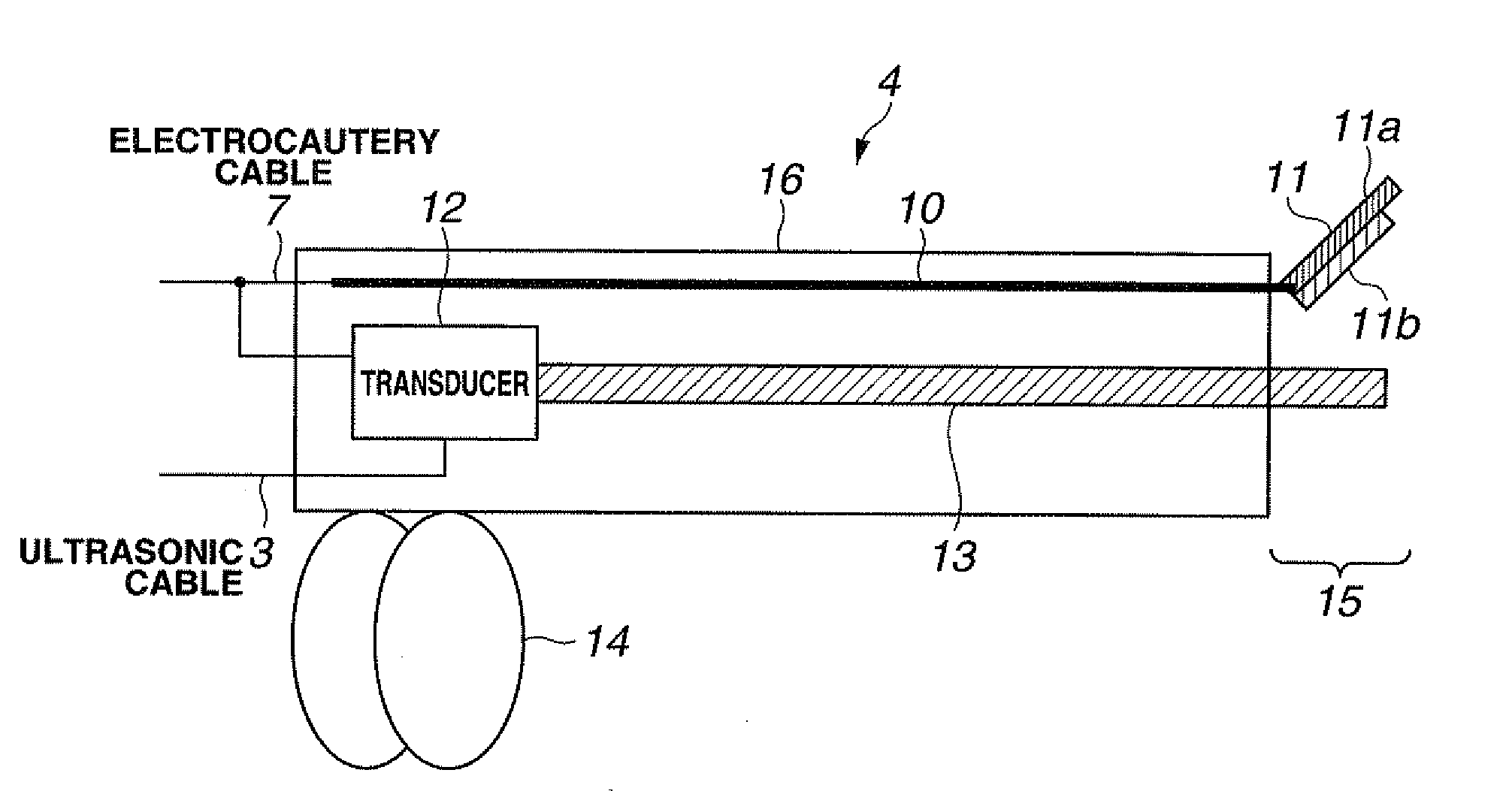
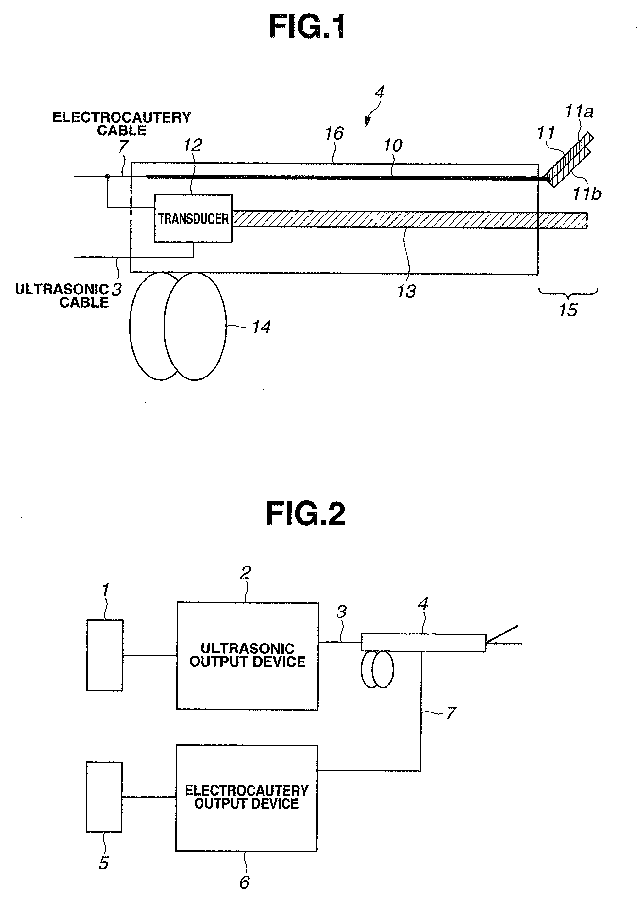
[0021]Hereinafter embodiments of the present invention are described with reference to the drawings. FIG. 1 is an explanatory diagram showing an ultrasonic scissors with electrocautery which is a surgical instrument according to the present invention. In addition, FIG. 2 is a block diagram showing a configuration of a whole system including the surgical instrument of FIG. 1.

[0022]First, description will be made on the configuration of the whole system with reference to FIG. 2.

[0023]An ultrasonic scissors with electrocautery 4 is connected to an ultrasonic output device 2 via an ultrasonic cable 3. To the ultrasonic output device 2 is connected an ultrasonic foot switch 1. The ultrasonic foot switch 1 instructs the ultrasonic output device 2 to turn on and off the ultrasonic output based on user operation. The ultrasonic output device 2 generates ultrasonic output based on the turning on / off instruction given by the ultrasonic foot switch 1. The ultrasonic output is applied to the ul...

second embodiment

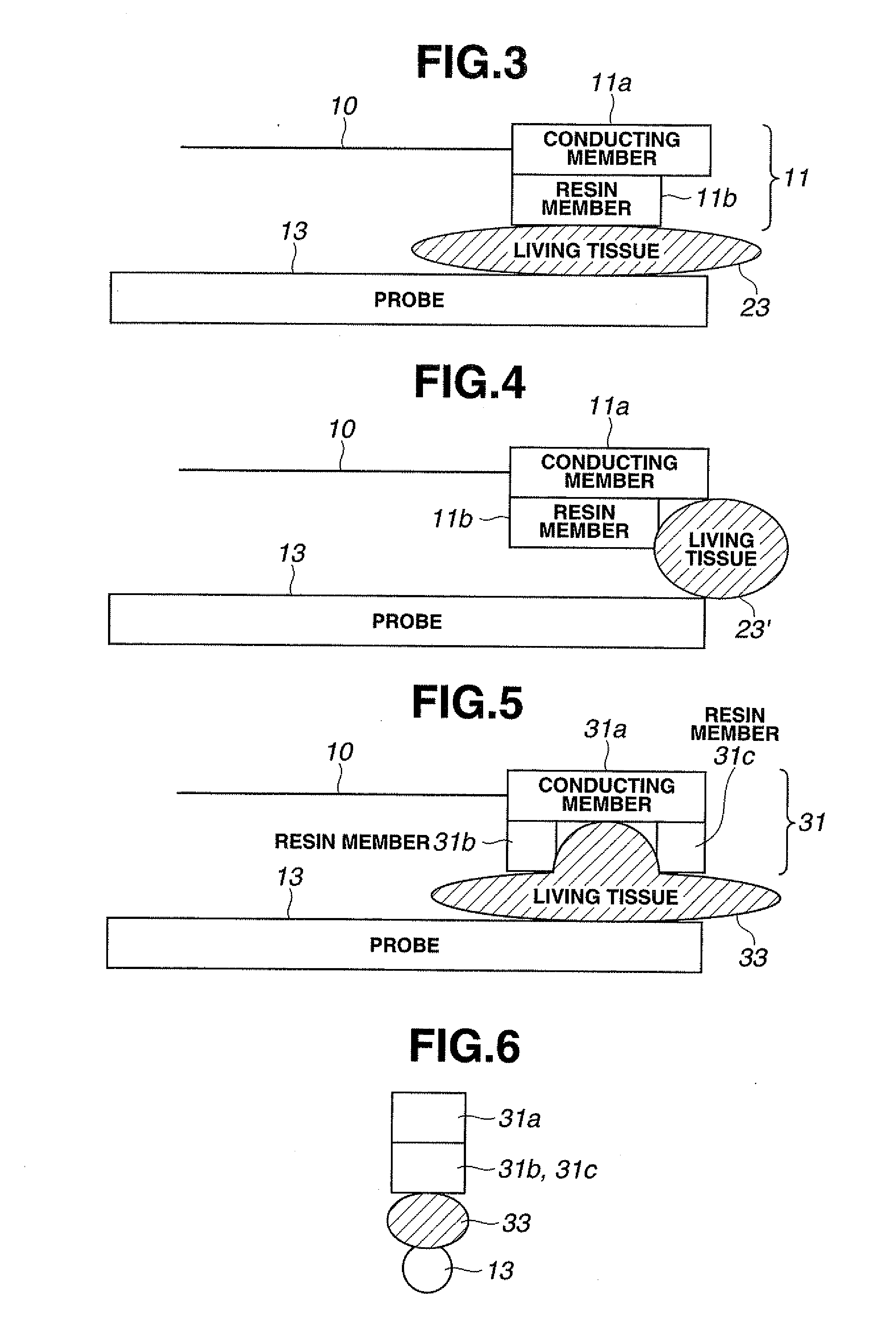
[0049]FIGS. 5 and 6 are explanatory diagrams showing the present invention. FIG. 5 is an explanatory diagram corresponding to FIG. 3, and FIG. 6 illustrates a state where FIG. 5 is seen from a distal end direction of the probe 13.

[0050]The present embodiment is different from the first embodiment in that a grasping member 31 is used instead of the grasping member 11.

[0051]The grasping member 31 has a two-layer structure of a conducting member 31a and resin members 31b, 31c. The conducting member 31a is connected with the transmitting member 10 (see FIG. 1), and high-frequency current is supplied thereto through the transmitting member 10. The conducting member 11a has the resin members 31b, 31c mounted on one surface on the probe 13 side. The resin members 31b, 31c are smaller in size than the conducting member 31a, and the conducting member 31 has a part not covered with the resin members 31b, 31c.

[0052]The grasping member 31 has a proximal end side rotatably supported by a pivot ...

third embodiment

[0062]FIGS. 7 and 8 are explanatory diagrams showing the present invention. FIGS. 7 and 8 correspond to FIGS. 5 and 6, respectively.

[0063]The present invention is different from the second embodiment in that a grasping member 41 is used instead of the grasping member 31.

[0064]The grasping member 41 has a two-layer structure of a conducting member 41a and resin members 41b, 41c. The conducting member 41a is connected with the transmitting member 10 (see FIG. 1), and high-frequency current is supplied thereto through the transmitting member 10. The conducting member 11a has resin members 41b, 41c mounted on one surface on the probe 13 side. The resin members 41b, 41c are smaller in size than the conducting member 41a, and the conducting member 41a has a part not covered with the resin members 41b, 41c.

[0065]The grasping member 41 has a proximal end side rotatably supported by a pivot not shown. The grasping member 41 moves and rotates around the pivot toward the probe 13 side, and th...


PUM


Abstract

A surgical instrument is provided including: an ultrasonic transducer for generating ultrasonic vibration; an ultrasonic probe for transmitting the ultrasonic vibration generated by the ultrasonic transducer to a distal end portion; a grasping member capable of grasping a living tissue as an object to be treated between the grasping member and a distal end portion of the ultrasonic probe by moving between positions close to and distant from the distal end portion of the ultrasonic probe; a conductive member configured of a conductive material for supplying high-frequency current to the living tissue, the conductive member being provided to the grasping member; and a non-conductive member configured of a non-conductive material and formed in a shape for blocking a contact between the conductive member and the ultrasonic probe and exposing a part of one surface of the conductive member on the ultrasonic probe side, the non-conductive member being provided to the grasping member so as to be located between the conductive member and the ultrasonic probe, thereby allowing high-frequency current to be effectively conducted to a living tissue.

Description

TECHNICAL FIELD[0001]The present invention relates to a surgical instrument capable of performing a treatment by high-frequency current in addition to a treatment of incision or coagulation of a living tissue by ultrasonic vibration.BACKGROUND ART[0002]Conventionally, there have been developed surgical instruments which utilize an endoscope for observing organs in a body cavity and the like by inserting an elongated insertion portion into the body cavity and enable various kinds of medical treatments under observation by an endoscope as needed.[0003]For example Japanese Unexamined Patent Application Publication No. 2004-216180 (hereinafter referred to as document 1) discloses an apparatus configured by combining an ultrasonic coagulation / incision apparatus and an electrocautery. The apparatus in the document 1 includes a treatment portion composed of a grasping member and a probe, and coagulates and incises a tissue by grasping the tissue by both of the members and ultrasonically vi...

Claims


Application Information

Patent Timeline
IPC IPC(8): A61N7/00A61B18/14
CPCA61B18/1442A61B17/320092A61B2017/320095
Inventor TAKAHASHI, HIROYUKI
Owner OLYMPUS CORP
Why Eureka
Try Eureka