Method for using high pressure refrigerant for leak checking a system

a high-pressure refrigerant and leak detection technology, applied in refrigeration components, transportation and packaging, light and heating equipment, etc., can solve problems such as reducing the amount of refrigerant available, affecting the operation of the air conditioning system, and affecting the operation of the system

Inactive Publication Date: 2009-11-05
SPX CORP
View PDF6 Cites 15 Cited by
  • Summary
  • Abstract
  • Description
  • Claims
  • Application Information

AI Technical Summary

Benefits of technology

[0005]Other embodiments provide a method for a refrigerant recovery unit that places high pressure refrigerant into a refrigeration system to test for refrigerant leaks, that includes a recovery circuit including a compressor configured to be coupled to a refrigerant system and to draw a refrigerant through the compressor; a controller in communication with the recovery circuit for controlling a transfer of the refrigerant through the compressor and for putting the compressed refrigerant into the refrigerant system; and a diversion circuit operatively engaged with said recovery circuit and said controller and operable to transfer the refrigerant from the compressor to the refrigerant system.
[0006]Still other embodiments provide a refrigerant recovery unit that places high pressure refrigerant into a refrigeration system to test for refrigerant leaks, that includes a fluid transfer means including a fluid compressing means configured to be coupled to a refrigerant system and to move a refrigerant through the fluid compressing means; and a controller in communication with the fluid transfer means for controlling a transfer of the refrigerant through the fluid compressing means and for putting the refrigerant received from the fluid compressing means directly into the refrigerant system.

Problems solved by technology

Over time, the air conditioning system may develops leaks, both large and small.
Leaking refrigerant not only reduces the amount of refrigerant available in the refrigerant system for cooling, but also contributes to greenhouse gas emissions into the atmosphere.
While previous methods to check for leaks have employed introducing a variety of gases such as nitrogen into the refrigeration system, these methods require separate equipment apart from the refrigerant recovery unit, and thus are not an efficient use of equipment or service time.

Method used


Image

  • Method for using high pressure refrigerant for leak checking a system
  • Method for using high pressure refrigerant for leak checking a system
  • Method for using high pressure refrigerant for leak checking a system

Examples


Embodiment Construction

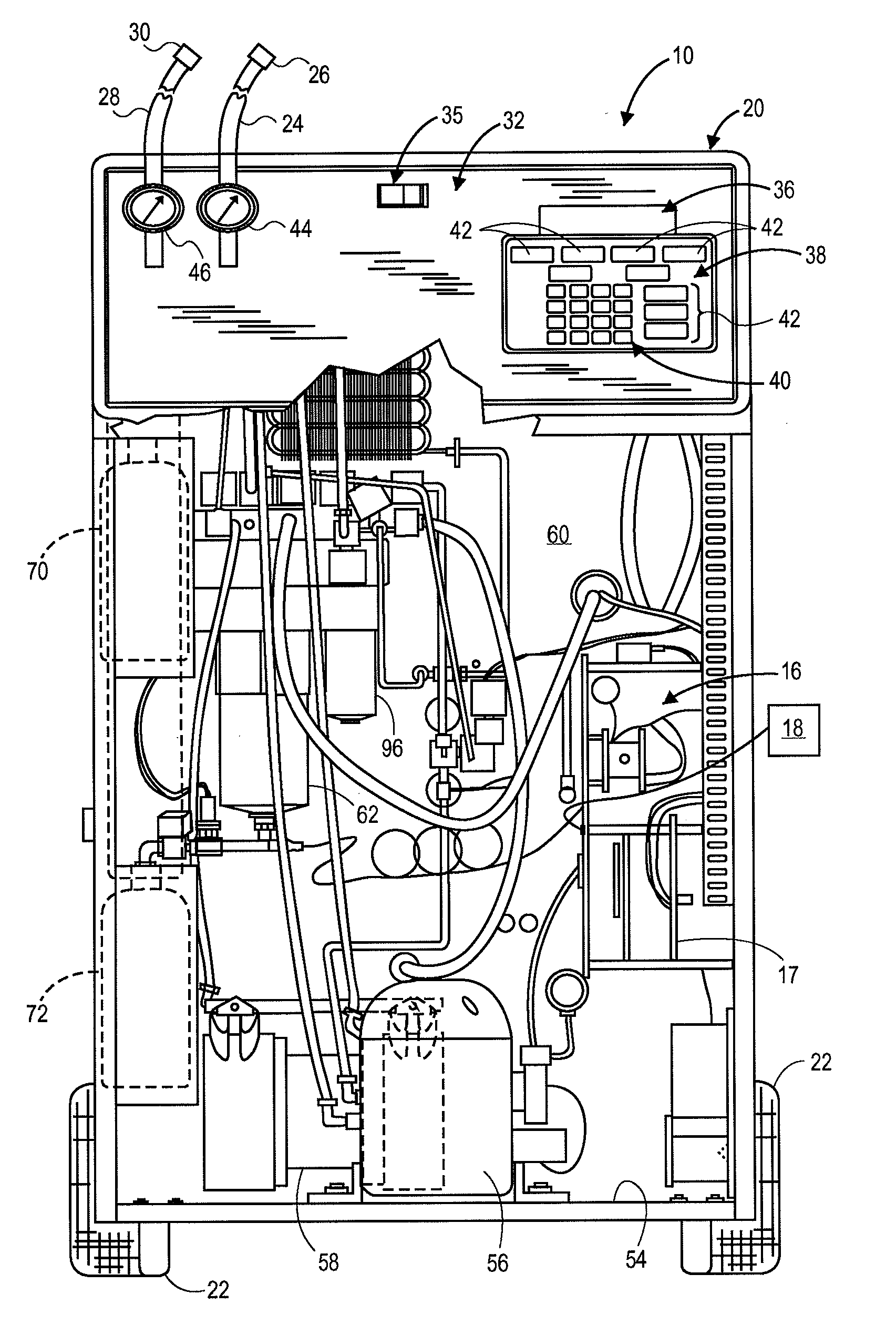
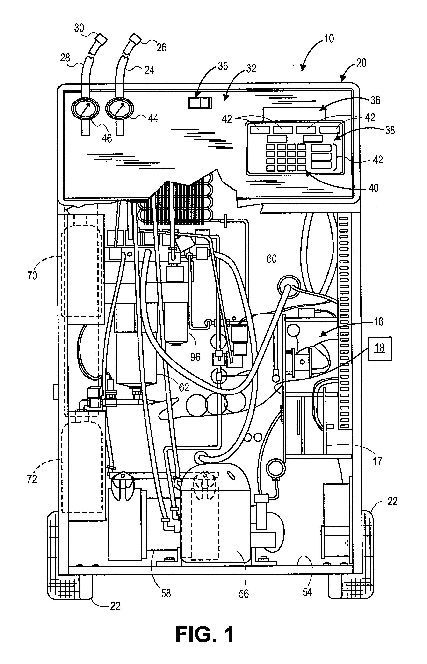
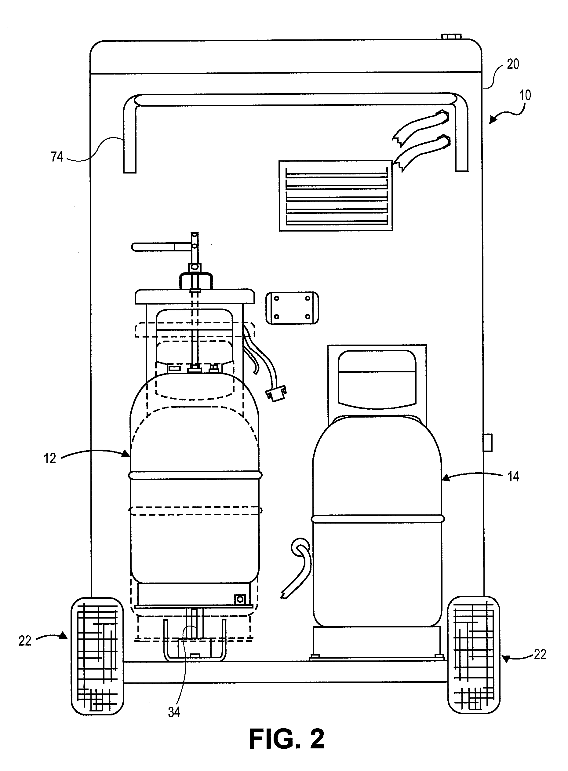
[0014]The invention will now be described with reference to the drawing figures, in which like numerals refer to like parts throughout. FIGS. 1-2 generally show one example of a portable recovery unit 10 for recovering and recycling refrigerant from a refrigerant system, such as in an automotive vehicle. The refrigerant recovery unit 10 is a machine mounted within a cabinet 20 supported by a pair of wheels 22, for portability. The unit 10 includes a first container or main tank 12 for holding a primary supply of refrigerant. The main tank 12 may also be referred to as an internal storage vessel (ISV). The primary supply of refrigerant or recovered refrigerant contains refrigerant that has been recovered from the air conditioning system. The unit 10 also includes a second container or auxiliary tank 14 for holding a secondary supply of refrigerant. The secondary supply of refrigerant has a known chemical composition, and is sometimes referred to as fresh refrigerant, virgin refrigera...


PUM


Abstract

A method for using refrigerant to check for a leak in a refrigerant system is provided that establishing fluid communication between a refrigerant recovery unit and a refrigerant system. The refrigerant recovery unit passes a refrigerant through the refrigerant recovery unit, compresses the refrigerant utilizing the refrigerant recovery unit, and transfers the compressed refrigerant from the refrigerant recovery unit directly into the refrigerant system. Additional refrigerant is added into the refrigerant system until a desired system pressure is reached, and then the refrigerant system is checked for leaks.

Description

FIELD OF THE INVENTION[0001]The disclosure relates generally to automotive vehicle air conditioning systems, and more specifically to refrigerant recovery units that can be utilized to check for leaks in the vehicle's air conditioning system.BACKGROUND OF THE INVENTION[0002]Portable refrigerant recovery units or carts are used in connection with the service and maintenance of refrigeration systems including an automotive vehicle's air conditioning system. The refrigerant recovery unit connects to the air conditioning system of the automotive vehicle to recover refrigerant out of the system, separate out oil and contaminants, and recharge the system with additional refrigerant.[0003]Over time, the air conditioning system may develops leaks, both large and small. Therefore, equipment is needed to check for these leaks. Leaking refrigerant not only reduces the amount of refrigerant available in the refrigerant system for cooling, but also contributes to greenhouse gas emissions into th...

Claims


Application Information

Patent Timeline
Patent Type & Authority Applications(United States)
IPC IPC(8): F25B45/00F25B43/00
CPCB60H1/00585F25B45/00F25B2345/0052F25B2345/002F25B2345/001
Inventor MCMASTERS, MARK WILLIAM
Owner SPX CORP
Why Eureka
Try Eureka