Light emitting device having a pluralilty of light emitting cells and package mounting the same

a light emitting cell and light emitting device technology, which is applied in the manufacture of semiconductor/solid-state devices, semiconductor devices, electrical devices, etc., can solve the problems of difficult use easy damage of light emitting devices, and achieve the effects of promoting heat dissipation, preventing metal leads, and easy dissipation of heat generated by light emitting cells

Active Publication Date: 2009-11-05
SEOUL VIOSYS CO LTD
View PDF86 Cites 51 Cited by
  • Summary
  • Abstract
  • Description
  • Claims
  • Application Information

AI Technical Summary

Benefits of technology

[0013]Another object of the present invention is to provide a light emitting device, wherein a thermal load on the light emitting device can be reduced and light emission efficiency can be improved.
[0035]According to the present invention, there is provided a light emitting diode that can be driven through direct connection to an AC power source by employing serial light emitting cell arrays having a plurality of light emitting cells connected in series. Since a flip-chip type light emitting device having a plurality of light emitting cells connected in series is implemented, heat generated from the light emitting cells can be easily dissipated, thereby reducing a thermal load on the light emitting device and improving light emitting efficiency as well. Meanwhile, it is possible to provide a package that can be driven through direct connection to an AC power source by mounting the light emitting device thereon. Moreover, even though the plurality of light emitting cells are employed, the process of mounting the plurality of light emitting cells on a submount substrate or lead frame can be simplified since the plurality of light emitting cells are connected in series using connection electrodes.

Problems solved by technology

However, since such a light emitting device is repeatedly turned on and off depending on the phase of an AC power source, there is a problem in that the light emitting device may be easily damaged.
Accordingly, it is difficult to use a light emitting device for the purpose of general illumination by connecting it directly to a household AC power source.

Method used


Image

  • Light emitting device having a pluralilty of light emitting cells and package mounting the same
  • Light emitting device having a pluralilty of light emitting cells and package mounting the same
  • Light emitting device having a pluralilty of light emitting cells and package mounting the same

Examples


Embodiment Construction

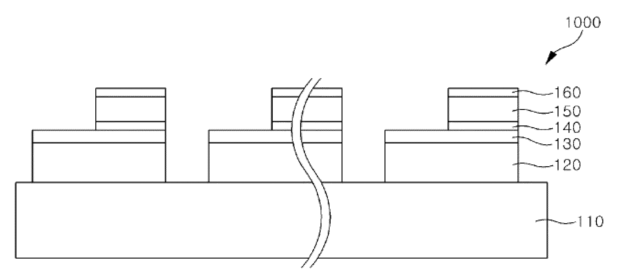
[0045]Hereinafter, embodiments of the present invention will be described in detail with reference to the accompanying drawings. The following embodiments are provided only for illustrative purposes so that those skilled in the art can fully understand the spirit of the present invention. Therefore, the present invention is not limited to the following embodiments but may be implemented in other forms. In the drawings, the widths, lengths, thicknesses and the like of elements can be exaggerated for convenience of illustration. Like reference numerals indicate like elements throughout the specification and drawings.

[0046]FIG. 2 is a circuit diagram illustrating an operational principle of a light emitting device having a plurality of light emitting cells according to an embodiment of the present invention.

[0047]Referring to FIG. 2, a first serial array 31 is formed by connecting light emitting cells 31a, 31b and 31c in series, and a second serial array 33 is formed by connecting othe...


PUM


Abstract

Disclosed is a light emitting device having a plurality of light emitting cells and a package having the same mounted thereon. The light emitting device includes a plurality of light emitting cells which are formed on a substrate and each of which has an N-type semiconductor layer and a P-type semiconductor layer located on a portion of the N-type semiconductor layer. The plurality of light emitting cells are bonded to a submount substrate. Accordingly, heat generated from the light emitting cells can be easily dissipated, so that a thermal load on the light emitting device can be reduced. Meanwhile, since the plurality of light emitting cells are electrically connected using connection electrodes or electrode layers formed on the submount substrate, it is possible to provide light emitting cell arrays connected to each other in series. Further, it is possible to provide a light emitting device capable of being directly driven by an AC power source by connecting the serially connected light emitting cell arrays in reverse parallel to each other.

Description

CROSS-REFERENCE TO RELATED PATENT APPLICATIONS[0001]This application is a continuation application of U.S. patent application Ser. No. 11 / 721,803, filed on Jun. 14, 2007, which is a U.S. national stage application of PCT International Application No. PCT / KR2005 / 003555, filed on Oct. 25, 2005, which claims priority of Korean Patent Application Nos. 10-2004-0105368, filed on Dec. 14, 2004, and 10-2005-0008309, filed on Jan. 29, 2005, which are hereby incorporated by reference for all purposes as if fully set forth herein.BACKGROUND OF THE INVENTION[0002]1. Field of the Invention[0003]The present invention relates to a light emitting device having a plurality of light emitting cells and a package having the same mounted thereon, and more particularly, to a light emitting device having a plurality of light emitting cells, which form serial arrays on a single substrate and can be directly driven using an AC power source, and a package having the same mounted thereon.[0004]2. Discussion o...

Claims


Application Information

Patent Timeline
Patent Type & Authority Applications(United States)
IPC IPC(8): H01L29/10H01L33/00H01L21/00H01L29/15H01L33/08H01L33/12H01L33/20H01L33/32H01L33/42H01L33/54H01L33/62H01L33/64
CPCH01L25/0753H01L27/153H01L2224/48091H01L2224/48247H01L2924/3025H01L2924/01322H01L2924/00014H01L2924/00
Inventor LEE, CHUNG HOONYVES, LACROIXYOON, HYUNG SOOLEE, YOUNG JU
Owner SEOUL VIOSYS CO LTD
Why Eureka
Try Eureka