

Repaired internal holding structures for gas turbine engine cases and method of repairing the same
a gas turbine engine and holding structure technology, applied in the direction of machines/engines, liquid fuel engines, turbines, etc., can solve the problems of affecting the service life of the turbine engine, the time-consuming task of manually welding the holding structure, and the need to repair the wear of the grooves,
- Summary
- Abstract
- Description
- Claims
- Application Information
AI Technical Summary
Problems solved by technology
Method used
Image

Examples
Embodiment Construction
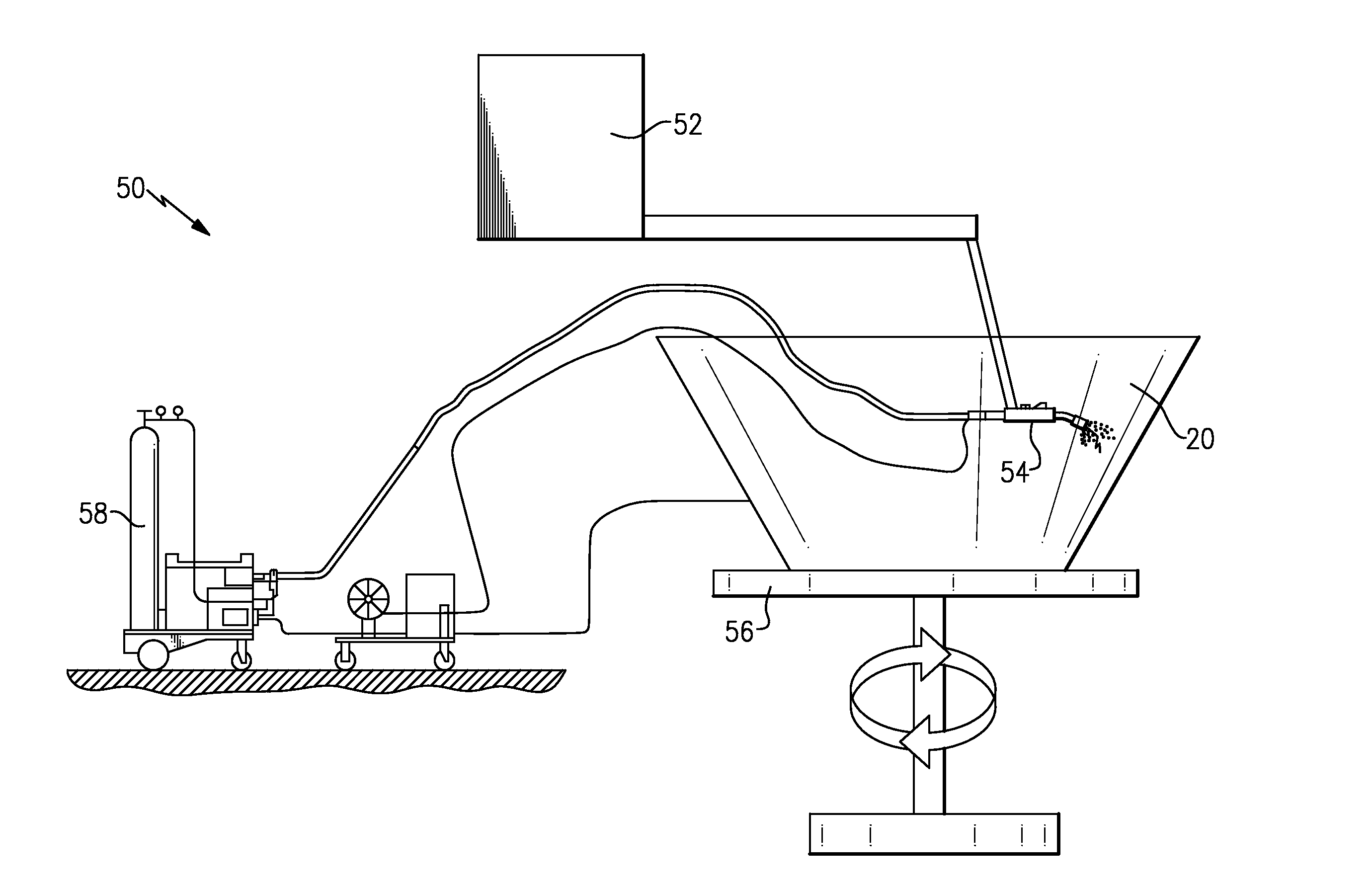
[0018]Historically, MIG welding processes have not been used to repair gas turbine engines for several reasons, including excessive porosity, spatter, and precision. With the improvements in these areas, the CMT process has been recognized as a viable alternative to TIG welding techniques on gas turbine engine components.
[0019]The CMT process can perform welding with relatively low heat input into the substrate. The low heat input results in less distortion to the welded features and a smaller heat affected zone. The deposition rate of the CMT process is quite faster than conventional TIG welding processes, which can reduce repair process times from hours to minutes.
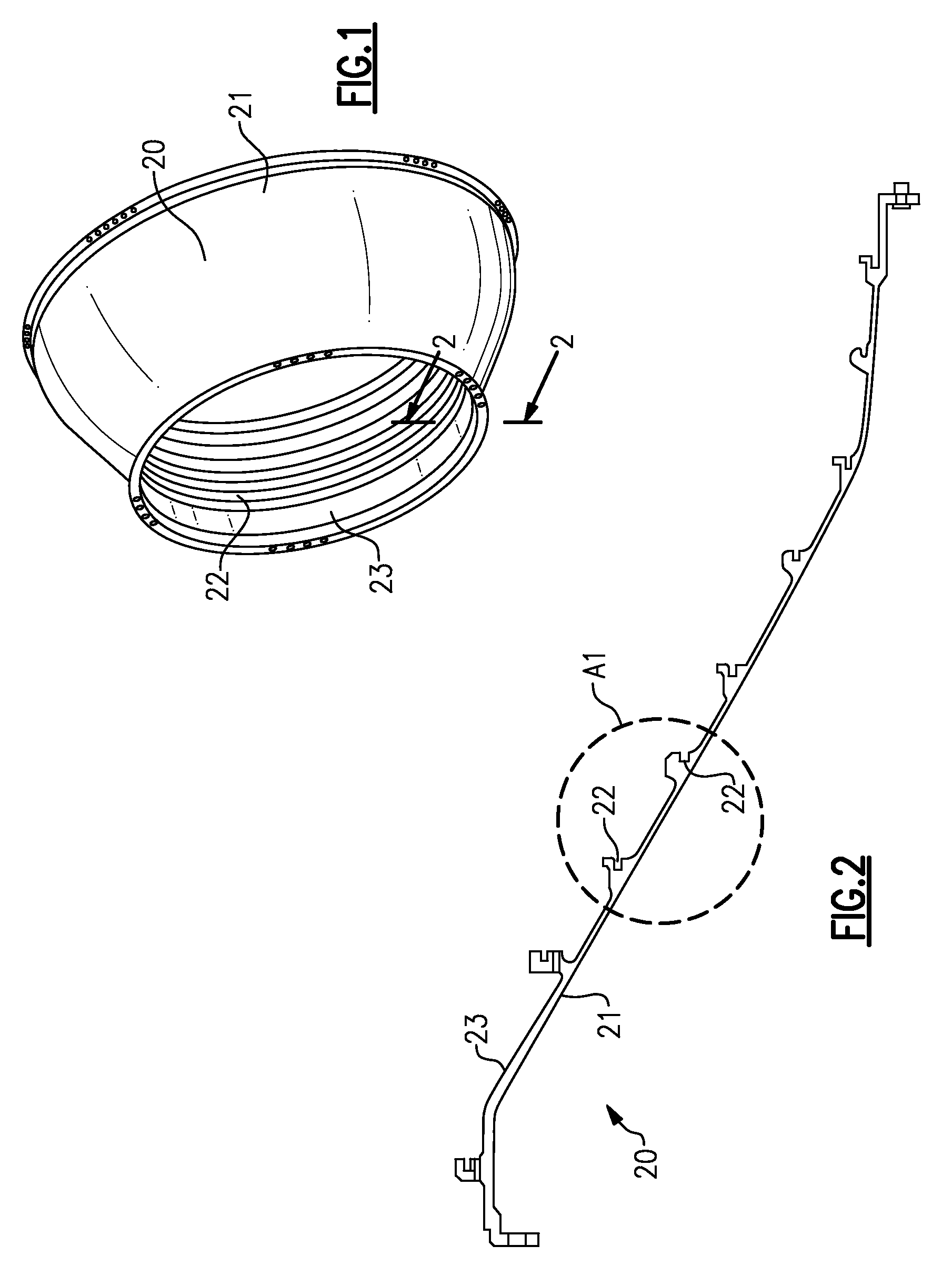
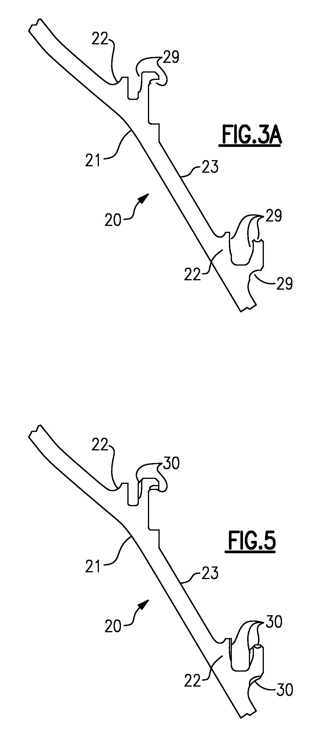
[0020]A case 20 for a gas turbine engine is illustrated in FIG. 1. The case 20 is a low pressure turbine case. It should be appreciated that the case 20 may also be a high pressure turbine case, a compressor case or a diffuser case. Case 20 is defined by a body having a radially outer wall 21 and a radially inner wall 23...
PUM
| Property | Measurement | Unit |
|---|---|---|
| Pressure | aaaaa | aaaaa |
| Shape | aaaaa | aaaaa |
Abstract
Description
Claims
Application Information