Foldable Firearm

a firearm and folding technology, applied in the field of firearms, can solve the problems of inhibiting streamlining design and prohibitively slow

Active Publication Date: 2009-11-12
MAGPUL INDUSTRIES
View PDF1 Cites 81 Cited by
  • Summary
  • Abstract
  • Description
  • Claims
  • Application Information

AI Technical Summary

Benefits of technology

[0007]To accomplish these objectives, the folding firearm comprises three main body components: a grip / magazine housing, a stock component and a receiver, containing the trigger assembly and action. Additional minor components, such as spring loaded opening assist and charging handle / latch assembly are utilized to add functionality. A folding buttplate serves to cover the joint of the weapon when folded, hold the weapon together and becomes a cheek plate when the weapon is deployed. The weapon may be made to utilize current aftermarket parts, specifically from the GLOCK line of firearms, to aid in part replacement availability.

Problems solved by technology

Prior folding firearms are noted for being manually deployed, and therefore prohibitively slow in a surprise situation.
They also typically feature an out-of-profile single hinge which inhibits streamlining design.

Method used


Image

  • Foldable Firearm
  • Foldable Firearm
  • Foldable Firearm

Examples


Embodiment Construction

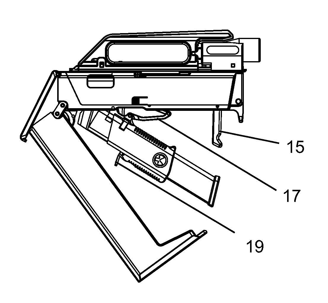
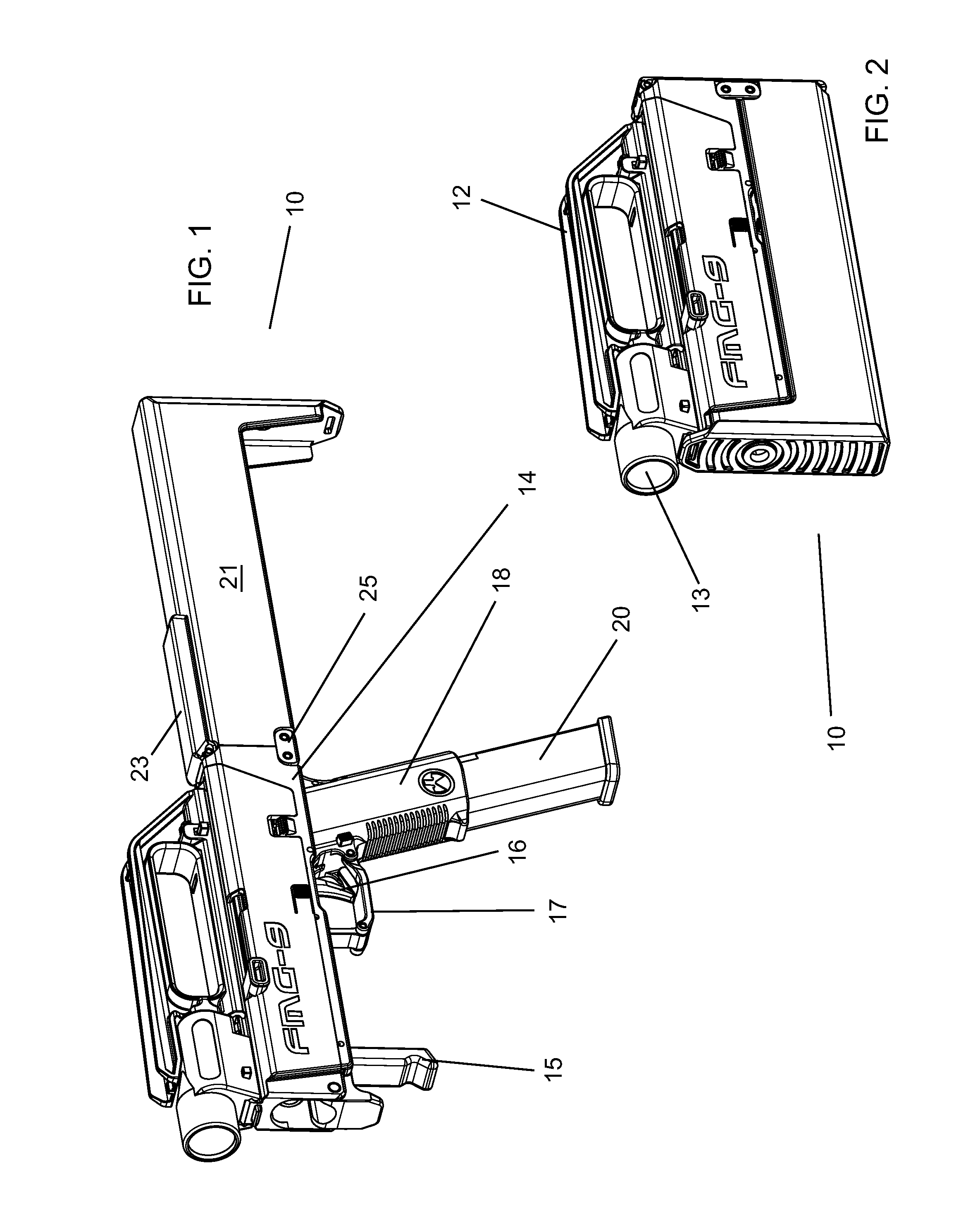
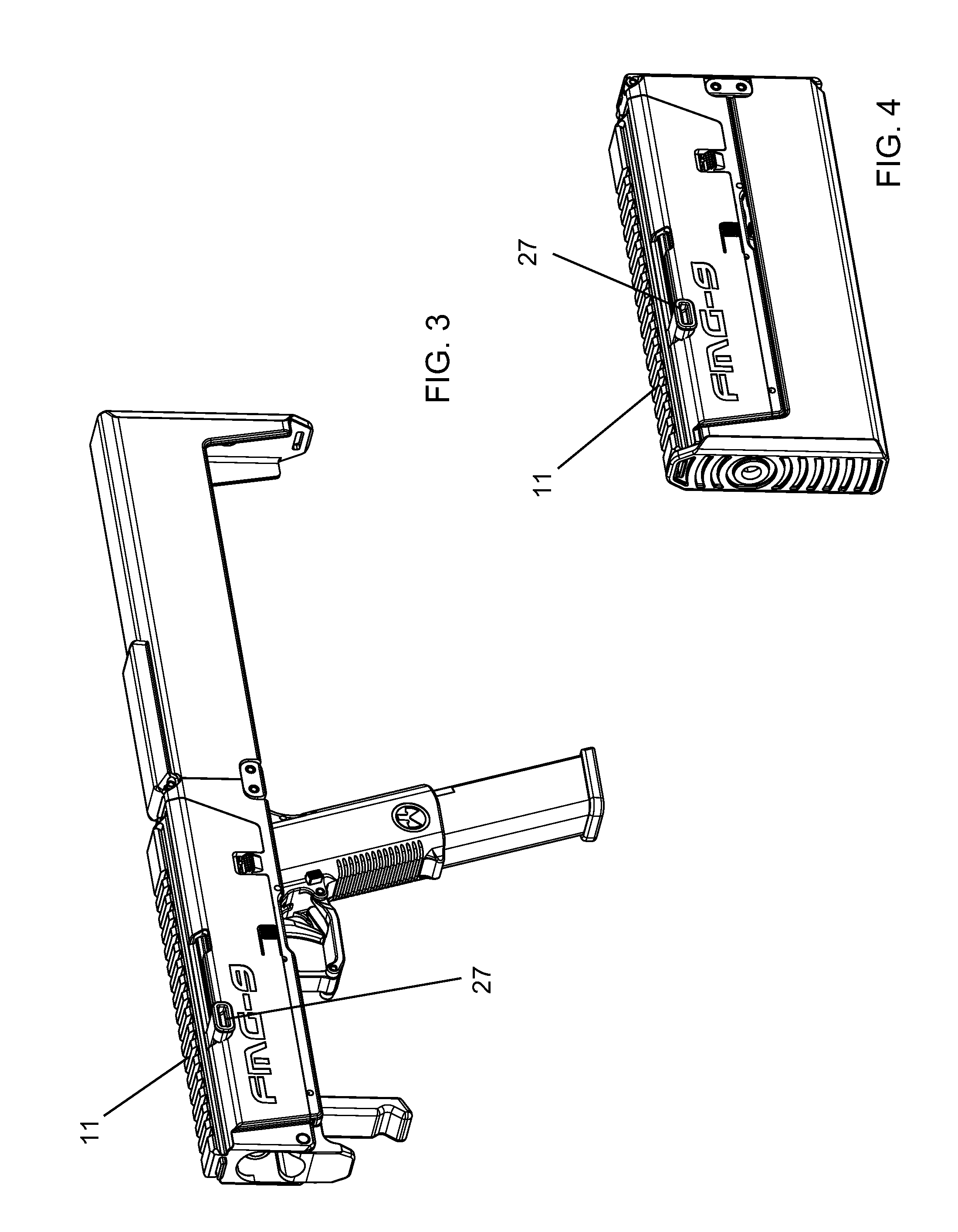
[0034]With reference now to the drawings, the preferred embodiment of the folding firearm is herein described. It should be noted that the articles “a”, “an”, and “the”, as used in this specification, include plural referents unless the content clearly dictates otherwise. The following reference numerals are used throughout this specification to denote the following parts of the firearm:[0035]10 Firearm, generally[0036]11 Rail[0037]12 Handle[0038]13 Light[0039]14 Receiver[0040]15 Fore end grip[0041]16 Trigger[0042]17 Trigger Guard[0043]18 Grip[0044]19 Grip Latch[0045]20 Magazine[0046]21 Stock[0047]22 Plate Notch[0048]23 Back Plate[0049]24 Hinge Springs[0050]25 Double Hinge[0051]26 Charging Handle Slot[0052]27 Charging Handle[0053]28 Spur[0054]29 Barrel[0055]30 Yoke[0056]31 Slide[0057]32 Charging Handle Return Spring[0058]33 Charging Handle Guide Rod[0059]34 Trigger Bar[0060]35 Firing Mechanism (generally)[0061]36 Guide Rod[0062]37 Recoil Spring

[0063]With reference to FIG. 1, the fir...


PUM


Abstract

The present invention is a spring-biased folding firearm that stows compactly and safely. The firearm has three main components: a stock, a receiver and a grip/magazine combination. In folding, the stock folds over the receiver, sandwiching the grip/magazine between the components. When folded, the magazine over-inserts into the grip housing, allowing the stock to clear and providing additional safety when stowed by isolating the ammunition feed. A buttplate latches over the open joint to contain the unit and further secure it. When stowed, the bolt is disengaged from the ammunition feed supply, preventing accidental firing, so a loaded round can be safely carried in the chamber—allowing for immediate use of the firearm upon opening. The weapon is deployed through single-handed actuation and is spring-assisted into firing position. Currently the firearm uses readily available aftermarket parts for easier replacement if necessary and does contain hardware for mounting accessories.

Description

CROSS-REFERENCES TO RELATED APPLICATIONS[0001]This Application is a non-provisional perfection of earlier filed U.S. Provisional Application No. 61 / 043,114, filed Apr. 7, 2008 and claims priority on the same, the prior application being incorporated by reference, in its entirety, herein.FIELD OF THE INVENTION[0002]The present invention relates to the field of firearms and more particularly relates to a firearm that folds into a compact storage mode while capable of deploying rapidly.BACKGROUND OF THE INVENTION[0003]Folding firearms are known in the prior art. Folding firearms are to be distinguished from weapons where a mere component, like a butt stock, folds over the weapon. Rather folding firearms are those that fold over themselves into a compact storage package. Prior folding firearms are noted for being manually deployed, and therefore prohibitively slow in a surprise situation. They also typically feature an out-of-profile single hinge which inhibits streamlining design.[0004...

Claims


Application Information

Patent Timeline
Patent Type & Authority Applications(United States)
IPC IPC(8): F41A11/04F41C23/12F41A9/61
CPCF41A3/66F41A5/04F41C23/12F41C9/02F41C23/04F41A11/04
Inventor BURT, ERIC C.FITZPATRICK, RICHARD M.MAYBERRY, MICHAEL T.
Owner MAGPUL INDUSTRIES
Why Eureka
Try Eureka