Blasting air tube with sleeve, and method

a technology of air tubes and air tubes, applied in the direction of blasting cartridges, weapons, weapon components, etc., can solve the problems of random and imprecise positioning, requiring tedious loading requirements, and inaccurate positioning of air tubes in a column of explosives

Inactive Publication Date: 2009-11-12
GOLDENROD PROPERTIES
View PDF12 Cites 6 Cited by
  • Summary
  • Abstract
  • Description
  • Claims
  • Application Information

AI Technical Summary

Benefits of technology

[0012]According to a primary object of the present invention, an inflatable air tube is provided including a sleeve member arranged concentrically about the upper end portion of the air tube to define a receptacle chamber for receiving

Problems solved by technology

AU 2004200940 required tedious loading requirements.
Random and imprecise positioning was the result.
The previous design resulted in inaccurate positioning of the air tubes in a column of explosives.
The

Method used


Image

  • Blasting air tube with sleeve, and method
  • Blasting air tube with sleeve, and method
  • Blasting air tube with sleeve, and method

Examples


Embodiment Construction

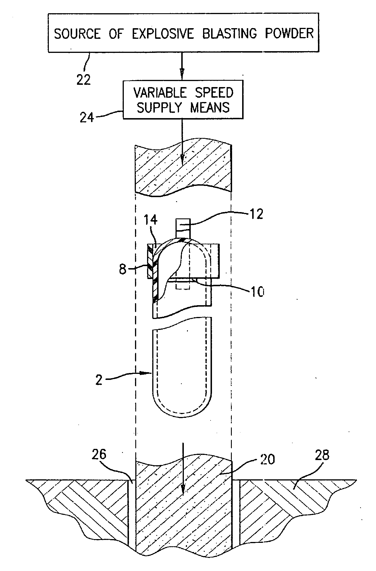
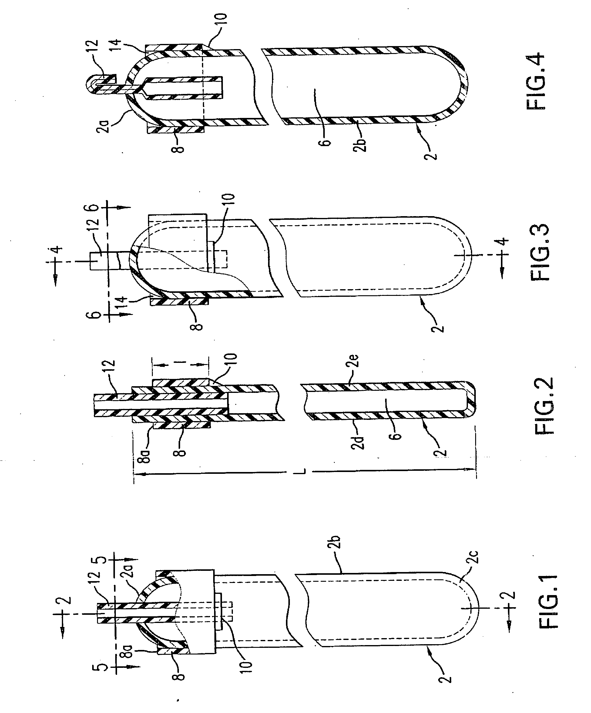
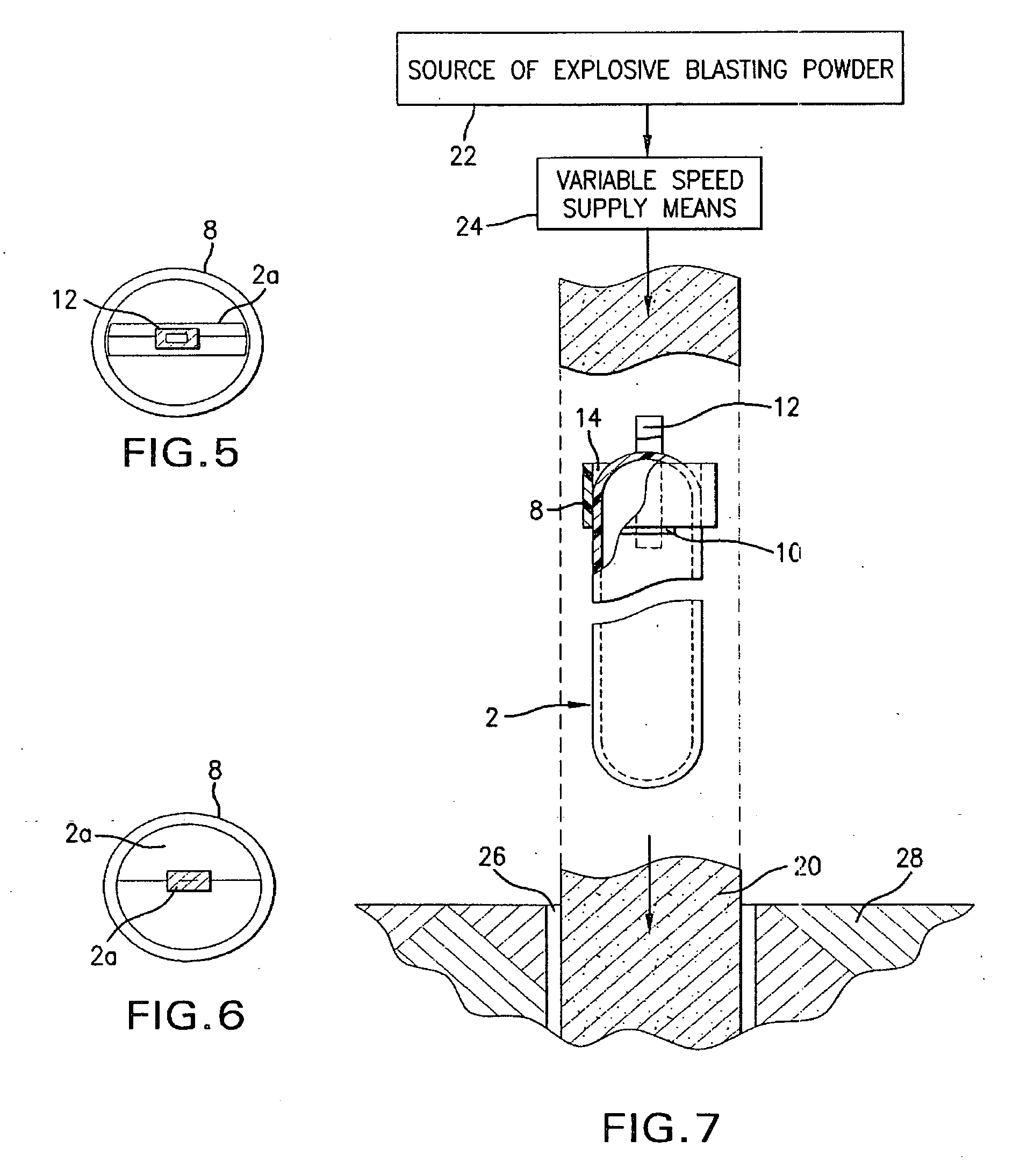
[0021]Referring first more particularly to FIGS. 1 and 2, the air tube 2 is illustrated in the collapsed flat condition and includes an upper end portion 2a, a vertically arranged intermediate portion 2b, and a lower end portion 2c. Prior to the introduction of air into the chamber 6 defined between the parallel air tube side walls 2d and 2e, the upper and lower ends of the air tube have a generally arch-shaped configuration. As shown in FIG. 1. In accordance with a characterizing feature of the present invention, a tubular sleeve member 8 is arranged concentrically about the air tube upper end portion 2a, which sleeve in the collapsed condition of FIGS. 1 and 2 is flat and is secured to the air tube side wall 2e by a fastening strip 10, such a heat seal seam, an adhesive strip, an adhesive layer between the sleeve member and the air tube, or the like. Preferably the upper edge 8a of the sleeve member is even with the adjacent edge of the arch-shaped end portion 2a, as shown in FIG....


PUM


Abstract

An inflatable air tube includes a sleeve member arranged concentrically about the upper end portion of the air tube to define a receptacle chamber for receiving a quantity of bulk explosive blasting powder, thereby to add weight to the air tube for positioning and stabilizing the same in the bulk explosive powder during the depositing of the powder into a blasting hole drilled into the ground. According to the method of the present invention, a plurality of accurate blasting patterns may be provided in the blasting powder column by timing the manual or mechanical insertion of the air tubes into the bulk blasting powder relative to the rate of supply of the powder from a source thereof.

Description

BACKGROUND OF THE INVENTION[0001]1. Field of the Invention[0002]An inflatable air tube includes a sleeve member arranged concentrically about the upper end portion of the air tube to define a receptacle chamber for receiving a quantity of bulk explosive blasting powder, thereby to add weight to the air tube for positioning and stabilizing the same in the bulk explosive powder during the depositing of the powder into a blasting hole drilled into the ground. A plurality of accurate blasting patterns may be provided in the blasting powder column by timing the manual or mechanical insertion of the air tubes into the bulk blasting powder relative to the rate of supply of the powder from a source thereof.[0003]2. Description of Related Art[0004]In the prior art air tube construction disclosed in the Robert Australian patent No. AU 2004200940 required tedious loading requirements. Briefly, these requirements include loading layers of explosives, then installing the air tubes, then loading ...

Claims


Application Information

Patent Timeline
IPC IPC(8): F42D1/08
CPCF42D1/08
Inventor ROBERT, VINCENT T.CAMPBELL, DUNCAN E.
Owner GOLDENROD PROPERTIES
Why Eureka
Try Eureka