Mask System

a mask and mask technology, applied in the field of mask systems, can solve the problems of increased treatment pressure, ineffectiveness of the nasal mask type patient interface, and mouth leakage, and achieve the effect of quiet exhalation gas washout, effective and simple us

Active Publication Date: 2009-11-12
RESMED LTD
View PDF103 Cites 127 Cited by
  • Summary
  • Abstract
  • Description
  • Claims
  • Application Information

AI Technical Summary

Benefits of technology

[0010]A mask system in accordance with a first aspect of the invention provides unobtrusive, comfortable, quiet, effective therapy to a patient's mouth and nasal passages. In one form, this is achieved by providing a mouth cushion with nasal prongs having a mask frame held in a stable position by a headgear including stabilizing elements. The headgear according to an embodiment of the present invention uniquely provide unobtrusive sealing for both the nose and mouth. The nasal prongs and mouth cushion according to an embodiment of the present invention can accommodate and seal with a wide range of different facial shapes. A vent according to an embodiment of the present invention provides quiet washout of exhaled gases. A swiveling elbow according to an embodiment of the present invention incorporates an anti-asphyxia valve that is effective and simple to use.
[0011]A form of headgear in accordance with an embodiment of the invention provides a sealing or retaining force against the mouth and against the nares. In one form the headgear includes a stabilizing element that has a generally serpentine shape that allows a retaining force be directed against the nares and allows the headgear to circumvent the eyes.
[0018]Still another aspect of the invention relates to a nasal prong for sealing with a nasal passage of a patient. The nasal prong includes a head portion structured to seal with the patient's nasal passage and a base portion structured to mount the nasal prong to a support structure. The base portion includes a horizontal segment, a radial segment, and a vertical segment that provide the base portion with a trampoline-like structure to add flexibility at the base portion.
[0022]Yet another aspect of the invention relates to a method for defining a cushion shape. The method includes selecting at least three points on the cushion, defining coordinates for each of the at least three points, and smoothly transitioning the shape of the cushion between the at least three points along the cushion perimeter.
[0030]Another aspect of the invention relates to a mask system for use between a patient and a device to deliver a breathable gas to the patient. The mask system includes a mouth cushion structured to sealingly engage around an exterior of a patient's mouth in use, a pair of nasal prongs structured to sealingly communicate with nasal passages of a patient's nose in use, an elbow to deliver breathable gas to the patient, and a headgear assembly to maintain the mouth cushion and the nasal prongs in a desired position on the patient's face. The nasal prongs each include a trampoline-like base that adds flexibility to the nasal prongs in use.
[0031]Another aspect of the invention relates to a mask system for use between a patient and a device to deliver a breathable gas to the patient. The mask system includes a mouth cushion structured to sealingly engage around an exterior of a patient's mouth in use, a pair of nasal prongs structured to sealingly communicate with nasal passages of a patient's nose in use, and a headgear assembly to maintain the mouth cushion and the nasal prongs in a desired position on the patient's face. The nasal prongs each include at least a first trampoline-like base that adds flexibility to the nasal prongs in use.

Problems solved by technology

A number of patients thus find that during sleep when muscles relax, mouth leak may occur.
Alternatively, some patients are naturally mouth breathers and thus find a nasal mask type patient interface ineffective.
Mouth leak is undesirable as, among other difficulties, it may result in noise, increased treatment pressure to compensate for the leak or an increased load on the nasal passages and potentially nasal obstruction or a runny nose.
Leak is a problem common to all designs of patient interface.
Typically, this is not achieved for the entire range of patients and some form of leak occurs.
The problem is heightened during sleep when the jaw moves and the head position changes.
This action can often serve to dislodge the mask and cause leak.
Since leak can be noisy and results in less-effective treatment, users often compensate by tightening the headgear more than is desired.
This is detrimental for patient comfort and can cause skin breakdown or irritation.
A further problem encountered by patients who are using full face, nasal or nose and mouth masks is that the portion of the patient interface that seals around the nasal bridge prevents the patient from wearing spectacles.
Additionally, it may give the sensation of being closed in, leading to a feeling of claustrophobia, particularly when combined with a mouth-sealing portion.
A further disadvantage is that any leaks that may occur can affect the sensitive area surrounding the eyes.

Method used


Image

  • Mask System
  • Mask System
  • Mask System

Examples


first embodiment

§1.1.3.1 First Embodiment Headgear

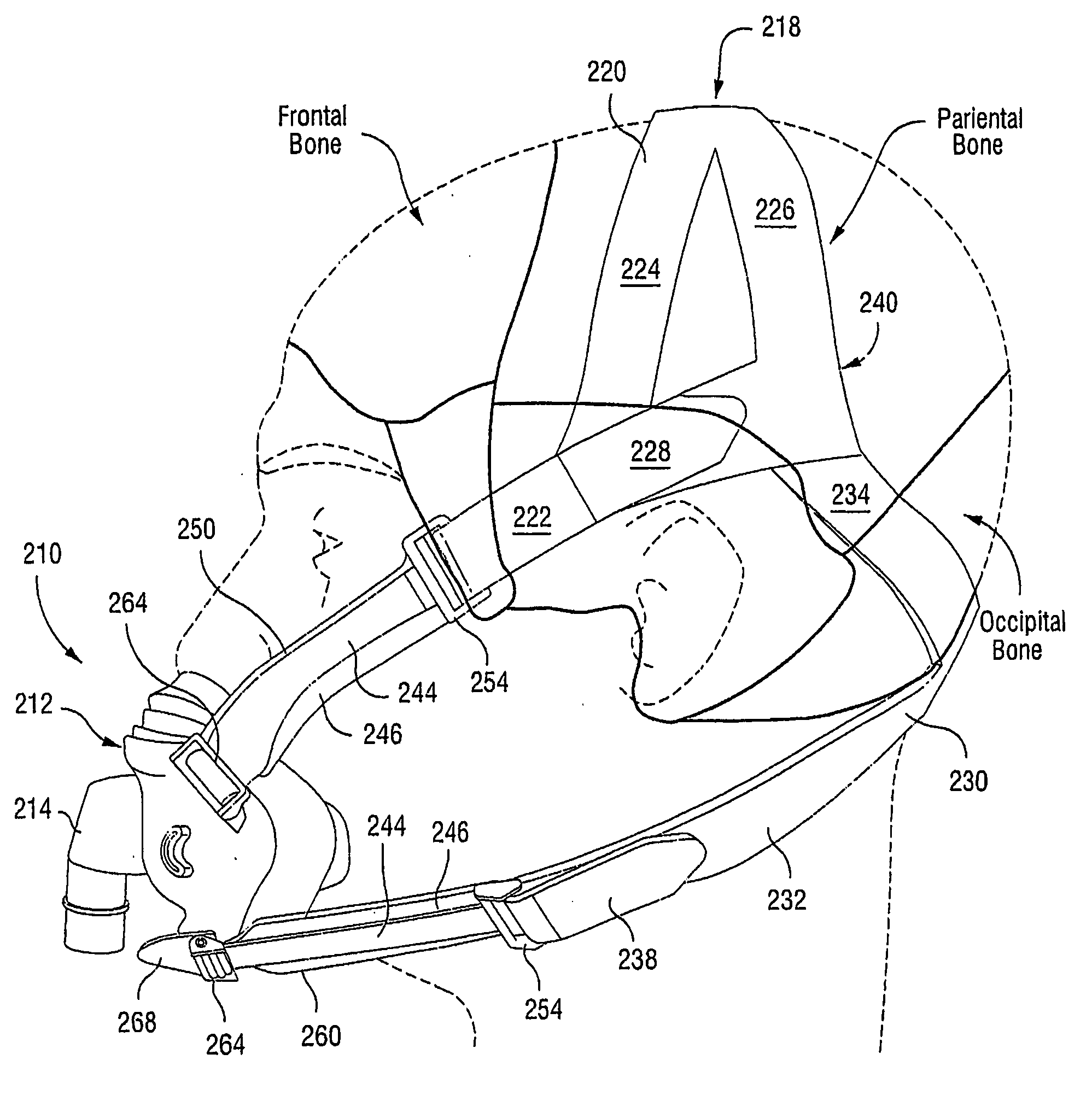
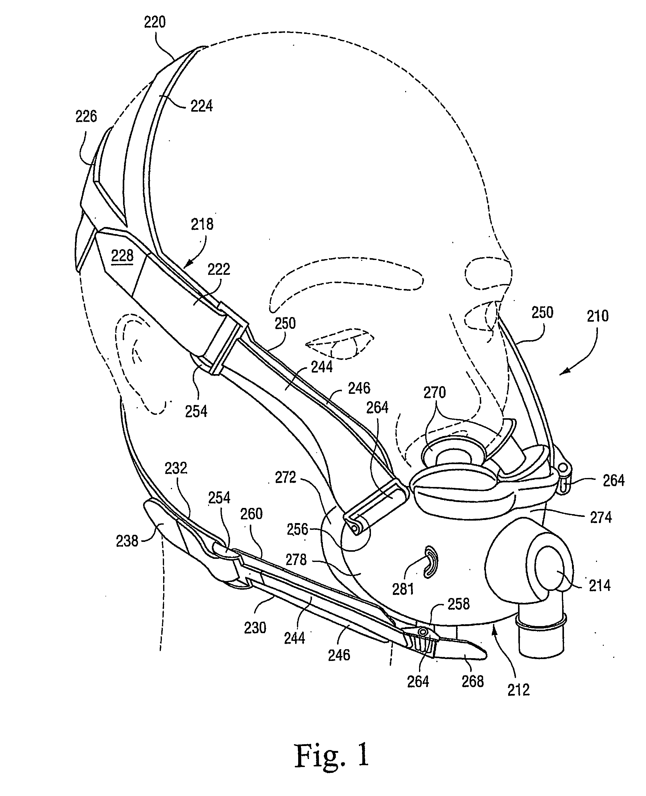
[0170]As illustrated in FIGS. 1, 11, and 12, the upper stabilizing straps 250 are removably connected to an upper portion of the frame 274, and the lower stabilizing straps 260 are removably connected to a lower portion of the frame 274.

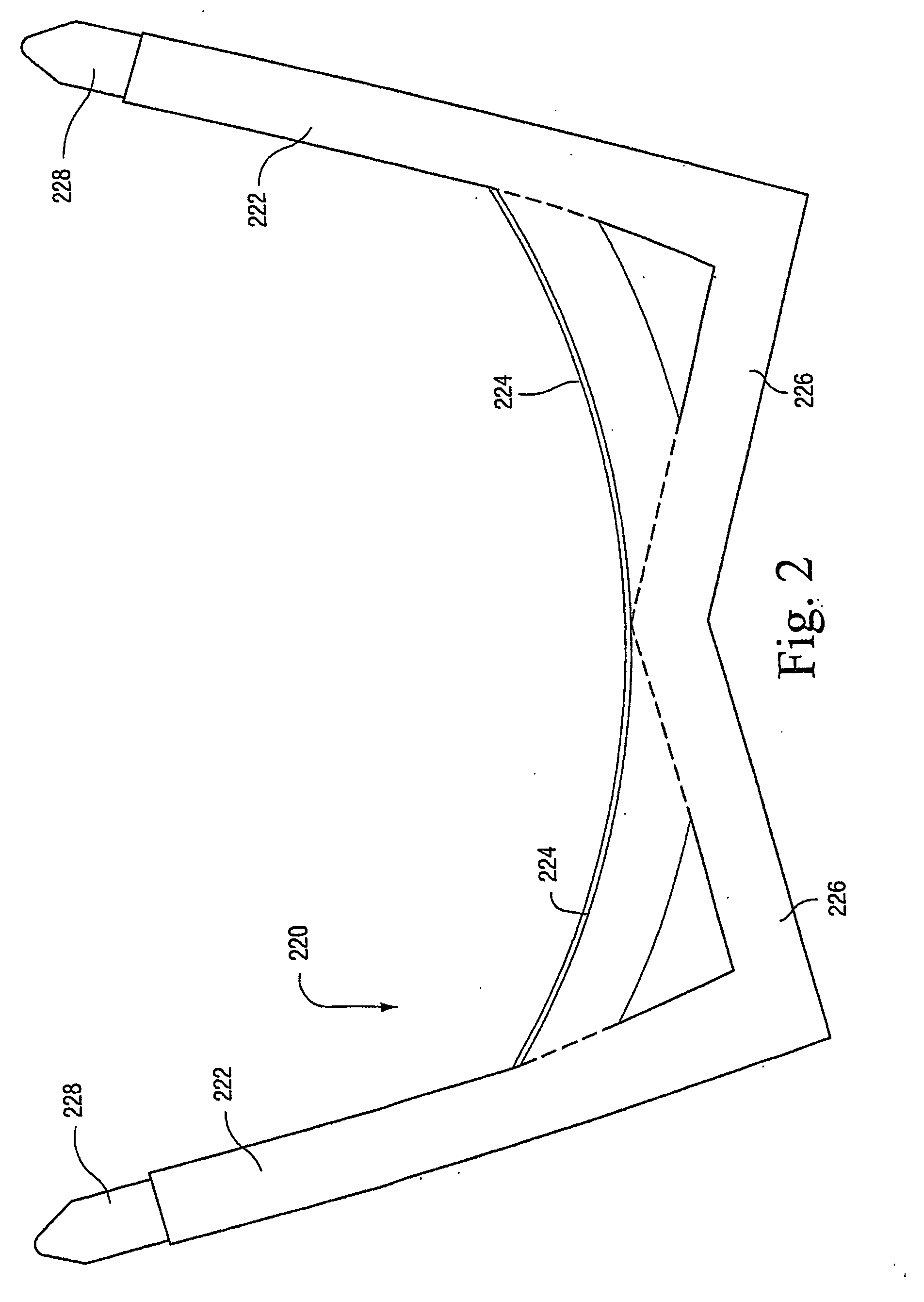
[0171]As shown in FIGS. 11 and 12, each of the upper and lower stabilizing straps 250, 260 includes a strap attachment member 254 secured at one end and a frame attachment member 264 secured at the opposite end. The strap attachment member 254 includes a crossbar that enables the end portion of the respective top and bottom strap portion 222, 232 to be wrapped around, in a known manner. The free end of each of the top and bottom strap portions 222, 232 includes a strip of Velcro® material 228,238 that engages the remainder of the strap portion to adjustably pull or secure the strap attachment member 254 in place. Thus, the length of the top and bottom strap portions 222, 232 maybe easily adjusted. However, other adju...

second embodiment

§1.1.3.2 Second Embodiment

[0178]In an alternative embodiment, the frame attachment member of each of the lower stabilizing straps 260 may be in the form of a locking clip 364. As shown in FIGS. 19-21, the locking clip 364 includes upper and lower arms 365, 367 that are resiliently flexible towards one another. Also, the upper arm 365 includes spaced-apart protrusions 369. In an embodiment, the locking clip 364 is molded in one-piece along with the yoke section 244 of the respective lower stabilizing strap 260. Alternatively, the locking clip 364 maybe formed separately from the yoke section 244 and attached thereto, e.g., by an adhesive or rotational connection, etc.

[0179]As shown in FIGS. 22-23, the frame 274 is provided with clip receptacles 371 on each side frame member thereof. Each clip receptacle 371 includes spaced-apart slots 373. In use, each clip 364 is interlocked with a respective clip receptacle 371 by first moving the clip 364 into the respective clip receptacle 371 su...

third embodiment

§1.1.3.3 Third Embodiment

[0181]In another alternative embodiment, the frame attachment member of each of the upper and lower stabilizing straps 250, 260 may be in the form of a press-stud type interface. As shown in FIGS. 24-25, the end of each stabilizing strap 250, 260 includes a protruding stud 465. A soft flexible finger tab 468 is provided on the end of each stabilizing strap to facilitate engagement and disengagement to the frame 274.

[0182]The frame 274 is provided with stud receivers on each side frame member thereof. In use, each stud 465 is press-fit into a respective stud receiver. This arrangement allows the stabilizing straps 250, 260 to rotate with respect to the frame 274 to allow the mask system to align on the patient's face. In an alternative embodiment, the studs 465 may be provided on the frame 274 and the stud receivers may be provided on the stabilizing straps 250, 260.

§1.1.4 Alternative Stabilizing Systems

[0183]FIGS. 26-29 illustrate alternative embodiments for...


PUM

PropertyMeasurementUnit
thickaaaaaaaaaa
thicknessaaaaaaaaaa
thicknessaaaaaaaaaa

Abstract

A mask system for use between a patient and a device to deliver a breathable gas to the patient includes a mouth cushion, a pair of nasal prongs, an elbow, and a headgear assembly. The mouth cushion is structured to sealingly engage around an exterior of a patient's mouth in use, and the pair of nasal prongs are structured to sealingly communicate with nasal passages of a patient's nose in use. The elbow delivers breathable gas to the patient. The headgear assembly maintains the mouth cushion and the nasal prongs in a desired position on the patient's face. The headgear assembly provides a substantially round crown strap that cups the parietal bone and occipital bone of the patient's head in use.

Description

CROSS-REFERENCE TO APPLICATIONS[0001]This application claims the benefit of U.S. Provisional Application Nos. 60 / 687,453, filed Jun. 6, 2005, 60 / 702,581, filed Jul. 27, 2005, and 60 / 795,562, filed Apr. 28, 2006, each of which is incorporated herein by reference in its entirety.[0002]Also, PCT Application No. PCT / AU2004 / 001832, filed Dec. 24, 2004, is incorporated herein by reference in its entirety.FIELD OF THE INVENTION[0003]The present invention relates to a mask system for delivery of respiratory therapy to a patient. Examples of such therapies are Continuous Positive Airway Pressure (CPAP) treatment, Non-Invasive Positive Pressure Ventilation (NIPPV), and Variable Positive Airway Pressure (VPAP). The therapy is used for treatment of various respiratory conditions including Sleep Disordered Breathing (SDB) such as Obstructive Sleep Apnea (OSA).BACKGROUND OF THE INVENTION[0004]Mask systems form an interface between a patient and apparatus providing a supply of pressurized air or b...

Claims


Application Information

Patent Timeline
Patent Type & Authority Applications(United States)
IPC IPC(8): A61M16/06
CPCA61M16/06A61M16/0666A61M16/0683A61M16/0816Y10T29/49826A62B18/084A61M16/0605A61M16/0616A61M2210/0618A61M16/0622A61M16/0633A61M16/0825A61M2016/0661A61M2210/06A61M2210/0606A61M2210/0625A61M16/0875A61M16/08A62B9/02A61M16/20
Inventor LUBKE, STEVEN JOHNSMART, GREGORY SCOTTSCHEINER, RUPERT CHRISTIANOLDENBURG, ALISONVANDYKE, JAMES WILLIAM CHARLESSKIPPER, CHRITOPHER SCOTTREID, MICHAEL JOHNNELSON, TIMOTHY SHAWNKWOK, PHILIP RODNEYSELVARAJAN, KARTHIKEYAN
Owner RESMED LTD
Why Eureka
Try Eureka