Method and device for threading needles

a needle threading and needle threading technology, applied in the field of domestic sewing, can solve the problems of linear strength, breakage, and thin wire forming the loop is subject to rapid metal fatigue, and achieve the effects of long durability, improved threading efficiency, and improved threading efficiency

Inactive Publication Date: 2009-11-12
HEYWOOD JANE F
View PDF10 Cites 14 Cited by
  • Summary
  • Abstract
  • Description
  • Claims
  • Application Information

AI Technical Summary

Benefits of technology

[0008]The principal object of the invention is to provide a non-metallic needle threading device and method of use thereof that is safer to use, more efficient in operation and of long durability. These and other objects and advantages will become more apparent hereinafter.

Problems solved by technology

One of the properties of threads and yarns used in the sewing field for stitching, embroidery and the like is that they have no linear strength and tend to be limp, flimsy or pliant and therefore bend during a needle threading exercise.
Besides the handling sequence, the problem with all such prior needle threaders is that the thin wire forming the loop is subject to rapid metal fatigue after a few repeated flexings as the loop is squeezed through the needle eye and breakage occurs.
This wire breakage not only makes the threader unusable, but creates the potential for causing the hand of the person wielding the threader to be pierced or punctured by the broken wire.

Method used


Image

  • Method and device for threading needles
  • Method and device for threading needles
  • Method and device for threading needles

Examples


Embodiment Construction

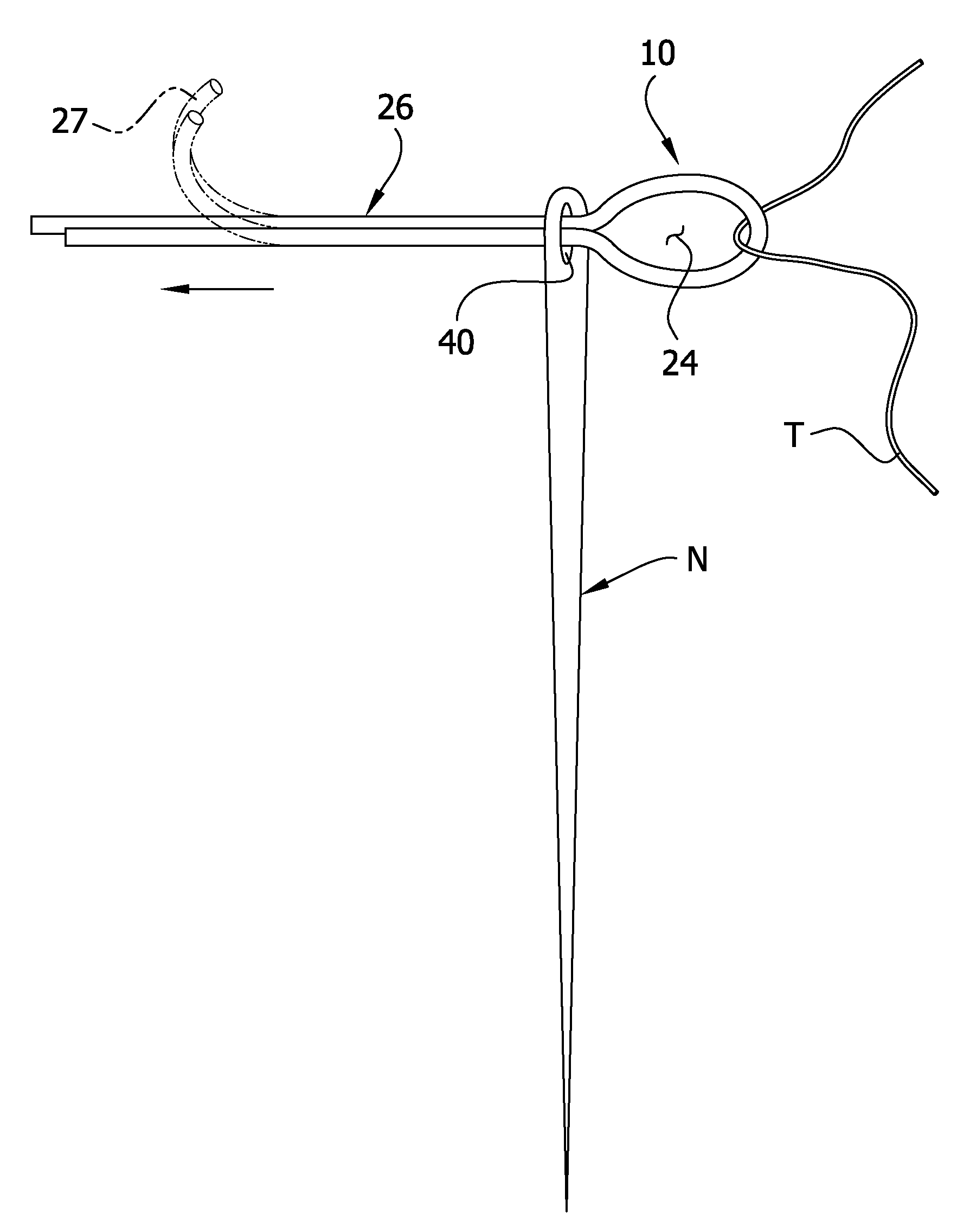
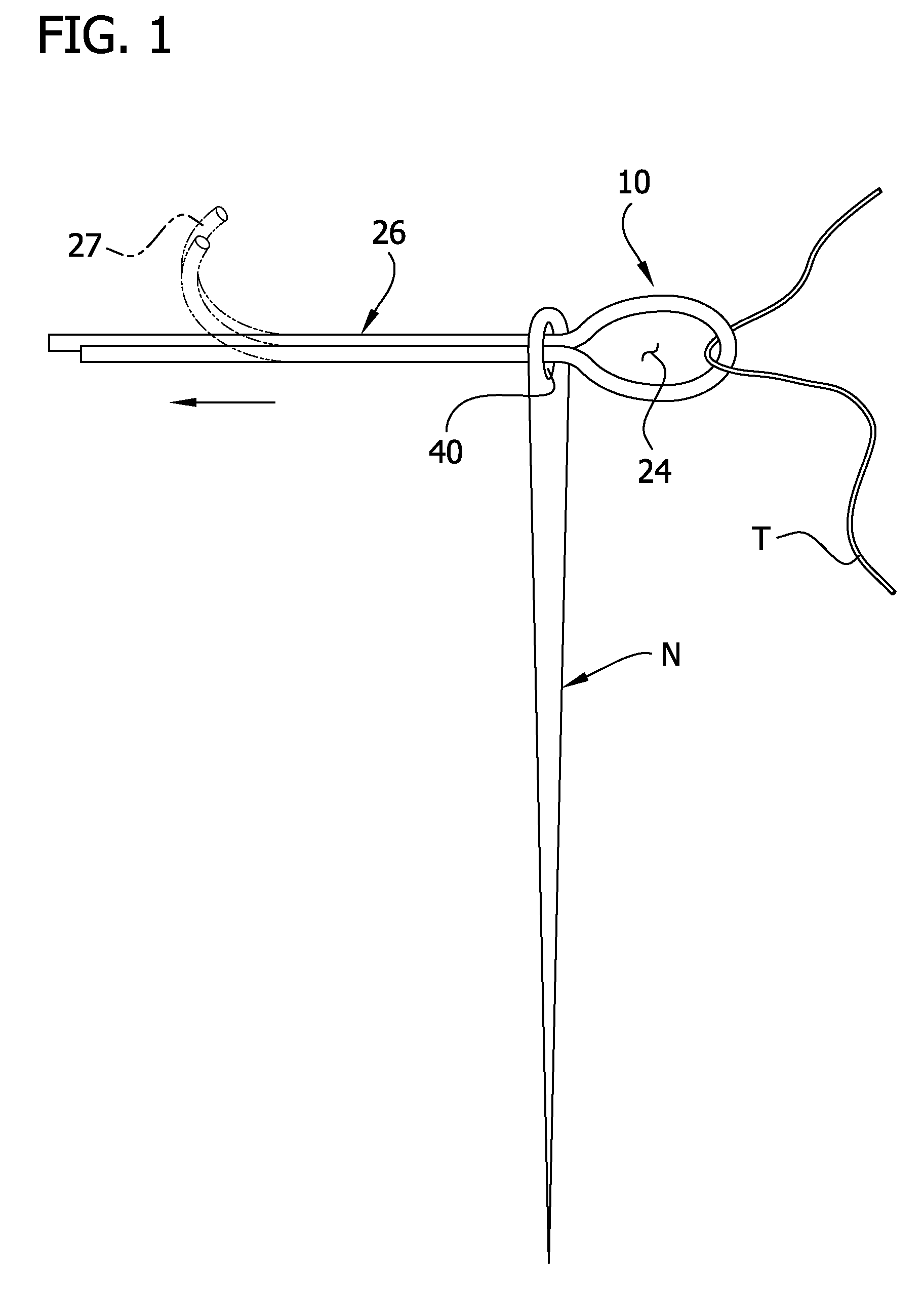
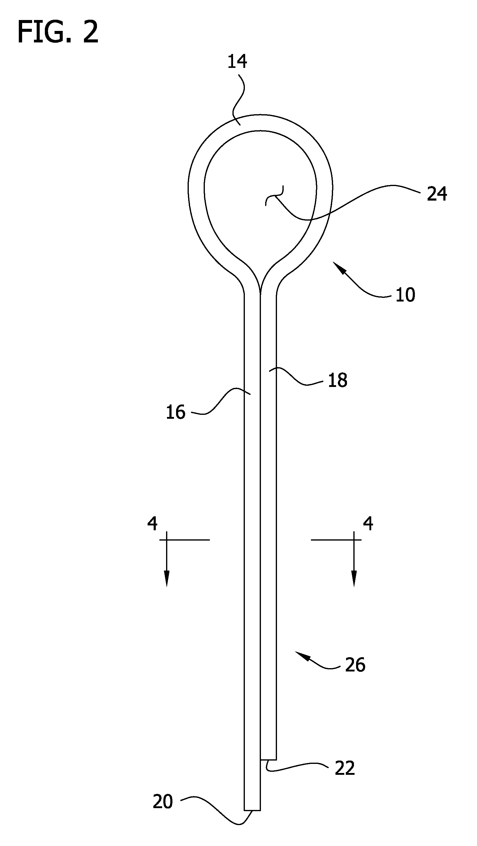
[0017]Referring to FIGS. 1 and 2 of the drawings, the invention in its simplest form is embodied in a needle threading device 10 (FIG. 2) formed from a single non-metallic length of microfilament 12 (FIGS. 3a and 3b) of a selected plastic material. The monofilament 12 has a central loop-forming zone 14 and outer first and second end zones 16, 18 with free ends 20, 22 respectively. The flexible monofilament 12 is bent or folded to form the central zone 14 into a closed loop or loophole or snare 24 (FIGS. 1, 2) with the end zones or portions 16, 18 extending outwardly in a side by side or parallel and abutting relationship to form a threading spike, spine or stem (shown generally at 26).

[0018]FIG. 1 also illustrates the method of the invention in which the device 10 is used to thread the elongate eyelet 40 of a typical needle N; and it should be noted that the device and method is also applicable to needles having round eyelets although the smaller eyelet will of course reduce the app...


PUM


Abstract

A method and device for inserting a strand of a selected thread or yarn through the eyelet of a needle, in which the device is made from an elongate, unitary non-metallic monofilament having end zones and an intermediate central zone forming a closed strand-carrying loophole; and the method including the steps of forming the device by bringing the end zones into a parallel relationship and bonding them together to form a threading stem and also form the central zone into the closed loophole, placing an end portion of the selected strand through the loophole, inserting the stem into the needle eyelet, and pulling the threading stem to draw the loophole and strand entirely through the needle eyelet.

Description

CROSS-REFERENCE TO RELATED APPLICATIONS[0001]This application claims the benefit of U.S. Provisional Application No. 61 / 052,489, filed May 12, 2008, which is hereby incorporated by reference in its entirety.FIELD OF THE INVENTION[0002]The invention relates generally to the domestic sewing field, and more particularly to an improved needle threading method and a device therefor.BACKGROUND OF THE INVENTION[0003]One of the properties of threads and yarns used in the sewing field for stitching, embroidery and the like is that they have no linear strength and tend to be limp, flimsy or pliant and therefore bend during a needle threading exercise. Thus most persons dampen the end of the thread strand to stiffen it enough to be inserted into the eyelet of a needle. Even so it still requires some eye / hand coordination and dexterity, even for a skilled seamstress or tailor. For those of diminished eyesight or unsteady hands, some type of sewing aide in the form of a threading device has been...

Claims


Application Information

Patent Timeline
Patent Type & Authority Applications(United States)
IPC IPC(8): D05B87/00
CPCD05B87/02
Inventor YOUNGMAN, BEVERLY A.
Owner HEYWOOD JANE F
Why Eureka
Try Eureka