Drive control unit, drive control method and program thereof

Inactive Publication Date: 2009-11-12
SONY CORP
View PDF1 Cites 6 Cited by
  • Summary
  • Abstract
  • Description
  • Claims
  • Application Information

AI Technical Summary

Benefits of technology

[0007]However, with a trend of reducing the size of the camera and lens in recent years, it has been often difficult to install the reset sensor at an ideal position for the reason of, for example, restrictions of arrangement space. For such a lens, a distance from the reset sensor to the target position is increased so that the startup time is also increased, thereby possibly lowering its operability. Even if no extension of the startup time occurs, it is desirable to further reduce the startup time.
[0009]The lens of the camera has been described here and a quick, accurate startup processing is demanded in not only this example but also in various devices and members. In case where the image pickup device of a camera is moved, it is demanded that the image pickup device is moved rapidly to an accurate position and if any movable member such as a flash or cover is disposed, reducing the startup time improves the operability of the camera. As other devices, a device in which the movable member (moving object body) is moved to a predetermined position at the time of startup can be mentioned, such as a reproducing / recording device in which its reading / writing head is moved to a predetermined position of a disc like memory medium at the time of startup. In such a device, the startup time is demanded to be as short as possible and at that time, an accurate startup operation needs to be executed.
[0010]Accordingly, the present invention has been made in views of the above-described issues, and it is desirable to provide a novel and improved drive control unit, drive control method and program capable of reducing the startup time and preventing a malfunction due to an external force such as an impact.
[0018]The first external force detecting section may detect an external force applied to a moving object body which can be moved more easily back and forth in the single direction by the external force than the at least one of the second moving object bodies, as the first moving object body.
[0024]According to the embodiments of the present invention described above, any malfunction due to an external force such as a shock can be prevented while reducing the startup time.

Problems solved by technology

However, with a trend of reducing the size of the camera and lens in recent years, it has been often difficult to install the reset sensor at an ideal position for the reason of, for example, restrictions of arrangement space.
For such a lens, a distance from the reset sensor to the target position is increased so that the startup time is also increased, thereby possibly lowering its operability.
However, if the camera is dropped or the camera strikes an obstacle so that an impact is applied thereto, even the stepping motor suffers disengagement or a rotation of the motor due to an external force when the external force due to the impact exceeds its magnitude of some extent.
Thus, simply using the aforementioned method disables to detect a motion of the lens because sometimes the lens is moved while the power supply is turned off.

Method used


Image

  • Drive control unit, drive control method and program thereof
  • Drive control unit, drive control method and program thereof
  • Drive control unit, drive control method and program thereof

Examples


Embodiment Construction

[0042]Hereinafter, preferred embodiments of the present invention will be described in detail with reference to the appended drawings. Note that, in this specification and the appended drawings, structural elements that have substantially the same function and structure are denoted with the same reference numerals, and repeated explanation of these structural elements is omitted.

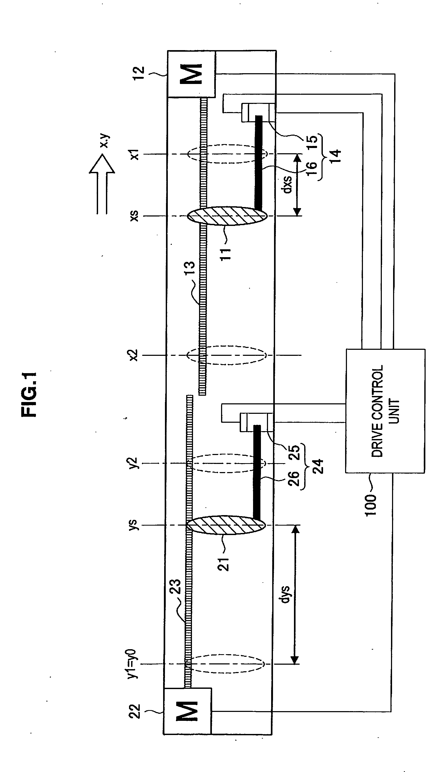
[0043]The drive control unit of each embodiment of the present invention can be applied to various apparatuses as long as it can move plural moving object bodies movable back and forth in the same direction. As the apparatus to which the drive control unit can be applied, for example, a still camera and video camera in which a plurality of lenses, image pickup device, flash, cover and the like are moved, and a recording reproduction device for moving a reading / writing head can be mentioned. Of course, this drive control unit can be applied to any mobile apparatus such as a mobile phone having a camera and a ...


PUM


Abstract

A drive control unit of the present invention includes: a first external force detecting section for detecting that an external force is applied to a first moving object body movable back and forth in a single direction; and a second initialization processing section which when it is detected that the external force is applied to the first moving object body by the first external force detecting section, moves at least one of second moving object bodies movable back and forth in the single direction to a predetermined second initial position and when it is not detected that the external force is applied to the first moving object body, does not move the second moving object body.

Description

[0001]The present application claims priority from Japanese Patent Application No. JP 2008-114279, filed in the Japanese Patent Office on Apr. 24, 2008, the entire content of which is incorporated herein by reference.BACKGROUND OF THE INVENTION[0002]1. Field of the Invention[0003]The present invention relates to a drive control unit, drive control method and program thereof.[0004]2. Description of the Related Art[0005]For example, cameras of fixed lens type include a plurality of lenses and the positions of these lenses need to be controlled at a high precision. In most cameras, a target position for moving the lens after its startup processing has been specified preliminarily (for example, infinite position of optical wide angle end (wide end)). For example, the camera uses a reset sensor for detecting a passage of the lens to move the lens to its target position. That is, the lens is once moved to pass the reset sensor and then, it is moved from the reset sensor to a target positi...

Claims


Application Information

Patent Timeline
IPC IPC(8): H04N5/225
CPCG02B7/102
Inventor SHIBATA, RYUJI
Owner SONY CORP
Why Eureka
Try Eureka