Method and apparatus for driving an LED

Active Publication Date: 2020-04-02
SIGNIFY HOLDING B V
View PDF0 Cites 4 Cited by
  • Summary
  • Abstract
  • Description
  • Claims
  • Application Information

AI Technical Summary

Benefits of technology

The patent text explains a method for controlling LED lights to achieve a consistent and efficient lighting system without causing flickering. The method uses a simple control signal to switch the LEDs on and off, resulting in a savings of power and a quick startup time. Overall, the text introduces a technical solution for controlling LED lights in a safe, reliable, and efficient manner.

Problems solved by technology

However, issues can arise at low dimming levels due to a hysteresis of the power provided by the switched-mode power supply to the LED.
In particular, when a pulse width of the PWM signal is low (e.g. at low dimming), each pulse of a PWM signal will be associated with a different average current through the LED, resulting in LED flicker.
A higher switching frequency and / or lower hysteresis of the switched-mode power supply can decrease this LED flicker, but may result in significant energy losses.
Synchronization of the PWM signal to the switching of the switched-mode power supply (e.g. using an enable pin of the switched-mode power supply) is an alternative solution, but this may cause significant start-up delay.
Moreover, the maximum duty cycle of the PWM signal will be limited, leading to an increased LED energy loss.

Method used


Image

  • Method and apparatus for driving an LED
  • Method and apparatus for driving an LED
  • Method and apparatus for driving an LED

Examples


Embodiment Construction

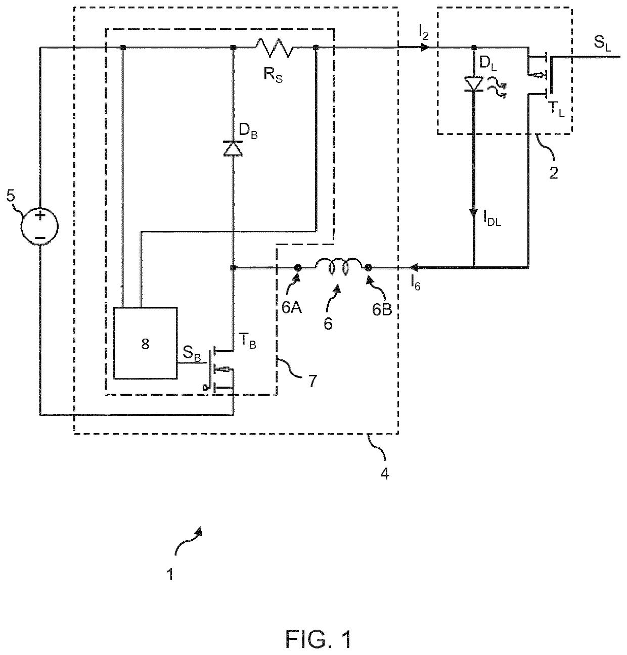
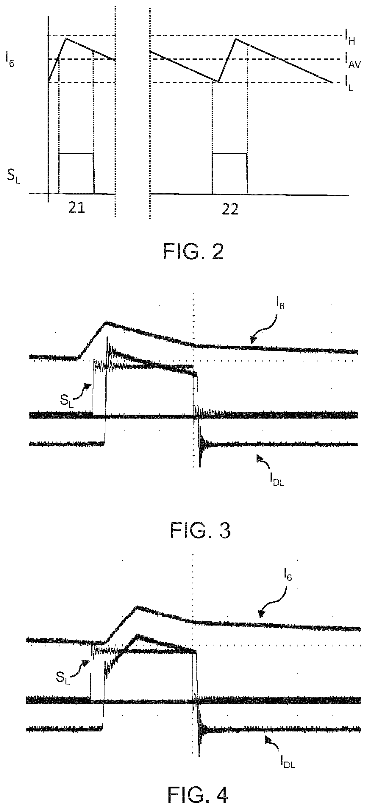
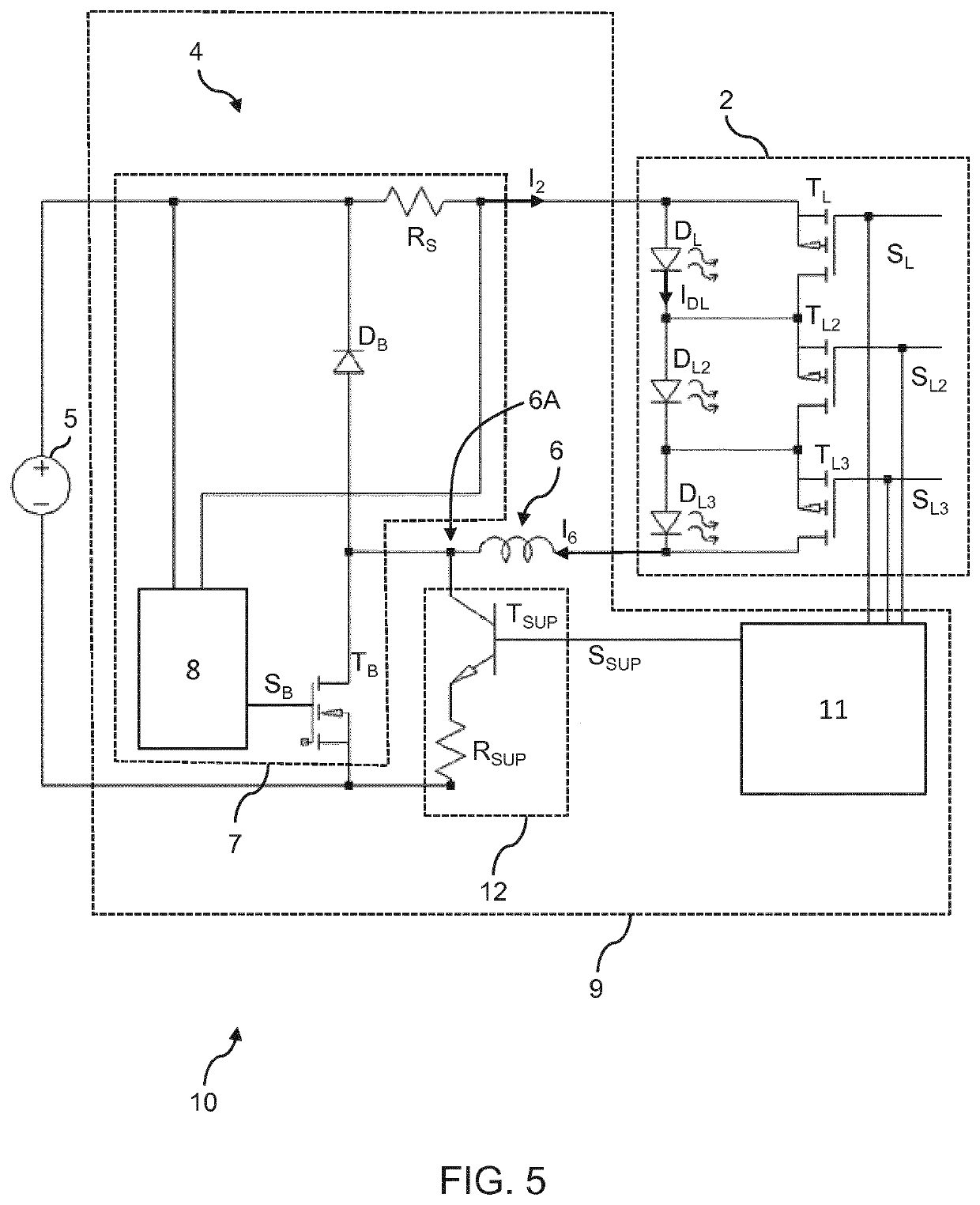
[0038]The invention provides a method and apparatus for overcoming LED flicker caused by an asynchronous control of an LED on or off state and a switched-mode power supply for the LED. There is provided a supplementary control system adapted to override a primary control system for the switched-mode power supply, and control an energy storage inductor of the switched-mode power supply. In particular, in response to an indicated desire to switch the LED on, the supplementary control system sets the current in the energy storage inductor to a predetermined level. In this way, when the LED is switched on, the current through the inductor is known and LED flicker is thereby reduced.

[0039]According to a concept of the invention, there is proposed a supplementary control system for a LED lighting driver having a switched-mode power supply. The supplementary control system ensures that a current through an inductor is at a predetermined value before an LED is switched to an on-state. This ...


PUM


Abstract

The invention provides a method and apparatus for overcoming LED flicker caused by an asynchronous control of an LED on or off state and a switched-mode power supply for the LED. There is provided a supplementary control system adapted to override a primary control system for the switched-mode power supply, and control an energy storage inductor of the switched-mode power supply. In particular, in response to an indicated desire to switch the LED on, the supplementary control system sets the current in the energy storage inductor to a predetermined level. In this way, when the LED is switched on, the current through the inductor is known and LED flicker is thereby reduced.

Description

FIELD OF THE INVENTION[0001]This invention relates to the field of lighting drivers for LEDs.BACKGROUND OF THE INVENTION[0002]Solid state lighting units, and in particular LED-based luminaires, are increasingly popular in homes, offices and other buildings. Besides their high efficiency they also attract consumers due to new design features, different color temperatures, dimming abilities etc.[0003]A variety of methods have been employed to enable dimming of an LED. For example, an on or off state of an LED may be controlled by a pulse-width modulation (PWM) signal operating according to a pulse-width modulation scheme. Alternatively, a lighting driver of the LED may comprise a switched-mode power supply adapted to alter an average voltage / current provided to the LED. Particularly advantageous embodiments employ both of these methods in order to provide an increased level of control over an LED output and to allow for extremely deep dimming.[0004]However, issues can arise at low dim...

Claims


Application Information

Patent Timeline
IPC IPC(8): H05B45/325H05B45/375H05B45/48H05B45/14H05B44/00
CPCH05B45/14H05B45/375H05B45/325H05B45/48H05B45/44H05B45/38H05B45/3725Y02B20/30
Inventor ZIJLMAN, THEO GERRITHONTELE, BERTRAND JOHAN EDWARDKAHLMAN, HENRICUS MARIUS JOSEPH MARIA
Owner SIGNIFY HOLDING B V
Why Eureka
Try Eureka