

Optical device provided with zooming mechanism
- Summary
- Abstract
- Description
- Claims
- Application Information
AI Technical Summary
Benefits of technology
Problems solved by technology
Method used
Image

Examples
first embodiment
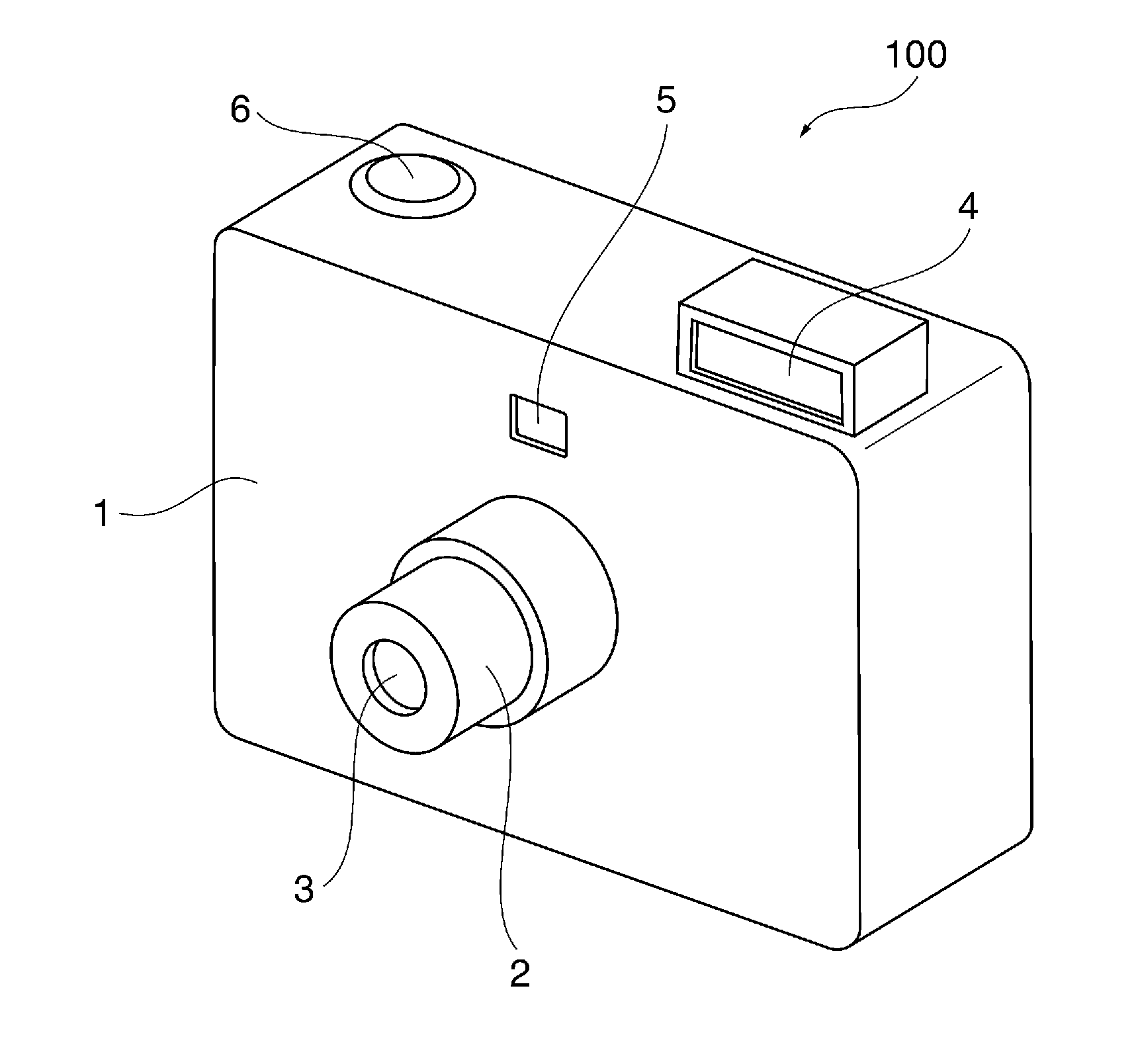
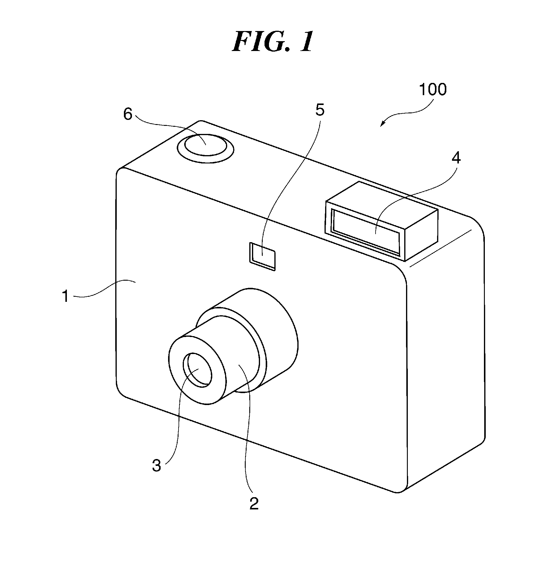
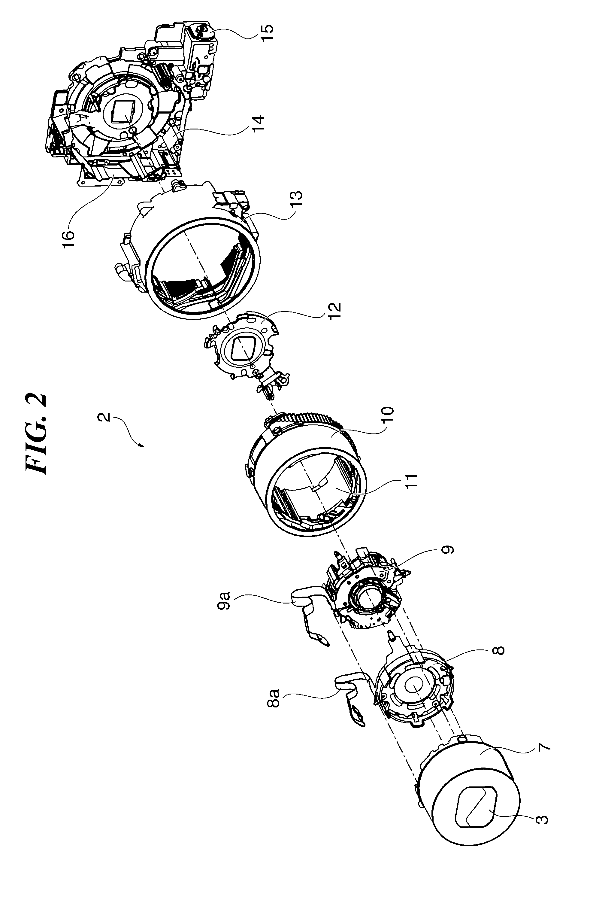
[0026]FIG. 2 is an exploded perspective view of the image pickup lens barrel 2 provided in the image pickup apparatus 100 of FIG. 1. The image pickup lens barrel 2 includes a first group lens barrel 7, a diaphragm unit 8, a second group lens barrel 9, a moving cam ring 10, a rectilinear motion barrel 11, a third group lens barrel 12, a fixed cylinder 13, an image pickup element holding member 14, a lens barrel drive motor 15, and a lens barrel flexible board 16.
[0027]The first group lens barrel 7 holds a first group image pickup lens L1 (see FIG. 5 to FIG. 7B), and is provided with the lens barrier device 3. The diaphragm unit 8 is provided with a diaphragm member as one of light quantity adjusting members, and adjusts the quantity of light guided to a film or an image sensor. Further, the diaphragm unit 8 is provided with a diaphragm flexible board 8a connected to the drive section of the diaphragm unit 8. The second group lens barrel 9 holds a second group image pickup lens L2 (se...
second embodiment
[0046]In the first embodiment, the portion of the image pickup surface side of the concave section 14b for accommodating the flexible boards 8a and 9a has a structure (a structure with the hole section 14g formed in the bottom section 14e) in which a bottom portion used for accommodating the flexible boards 8a and 9a in the image pickup lens barrel 2 is not provided. For this reason, as described above, it is necessary to close the hole section 14g by using the flat surface of the member on the image pickup surface side of the image pickup lens barrel 2, or by using a sheet member (not shown). In this case, there is a problem that the number of components is increased to increase the cost, and there is a possibility that damage, and the like, of the flexible boards 8a and 9a is caused by the friction at the time when the flexible boards 8a and 9a are made to slide on the surface of peripheral members.
[0047]In order to solve this problem, a second embodiment is configured such that t...
third embodiment
[0053]In the case where the shutter flexible board 9a is provided with an anti-vibration wiring pattern, it is expected to further increase the width of the shutter flexible board 9a. To cope with this, in the third embodiment, the image pickup element holding member 14 described in the first embodiment is modified.
[0054]FIG. 10 is a perspective view of a structure of an image pickup element holding member 34 according to a third embodiment. The image pickup element holding member 34 is different from the image pickup element holding member 14 according to the first embodiment in that a bottom section 34g connected to the bottom surface 14e is formed at each of both ends of the hole section 14g (see FIG. 3), and in that a through hole 34h resulting from the hole section 14g is formed between the two bottom sections 34g. The convex section 14a, both end portions of which are carved to leave a portion having a width equal to or less than the width of the through hole 34h that is not c...
PUM
 Abstract
Description
Claims
Application Information