Apparatus, Method, and Program Product for Image Processing

Inactive Publication Date: 2009-11-12
SEIKO EPSON CORP
View PDF5 Cites 19 Cited by
  • Summary
  • Abstract
  • Description
  • Claims
  • Application Information

AI Technical Summary

Benefits of technology

[0007]An advantage of some aspects of the present invention is to provide a technology whereby block noise can be reduced, while suppressing at least some of problems from occurring.
[0009]With this arrangement, the weak smoothing process is carried out in a case where variation rate of pixel values within the target pixel block is high, so that block noise can be reduced while suppressing problems such as image blurring.

Problems solved by technology

In some instances, non-reversible processes of this kind may give rise to block noise in the decoded image data (also called “block distortion”).
However, processes for reducing block noise may give rise to various problems in some instances.
For example, in some instances the processed image may become blurred; in other instances, processing may require considerable processing capability; or in yet other instances, highly noticeable block noise may remain.

Method used


Image

  • Apparatus, Method, and Program Product for Image Processing
  • Apparatus, Method, and Program Product for Image Processing
  • Apparatus, Method, and Program Product for Image Processing

Examples


embodiment 1

A.

B. Embodiment 2:

C. Embodiment 3:

D. Embodiment 4:

E. Embodiment 5:

F. Embodiment 6:

G. Embodiment 7:

H. Embodiment 8:

I. Embodiment 9:

J. Modified Embodiments:

A. Embodiment 1

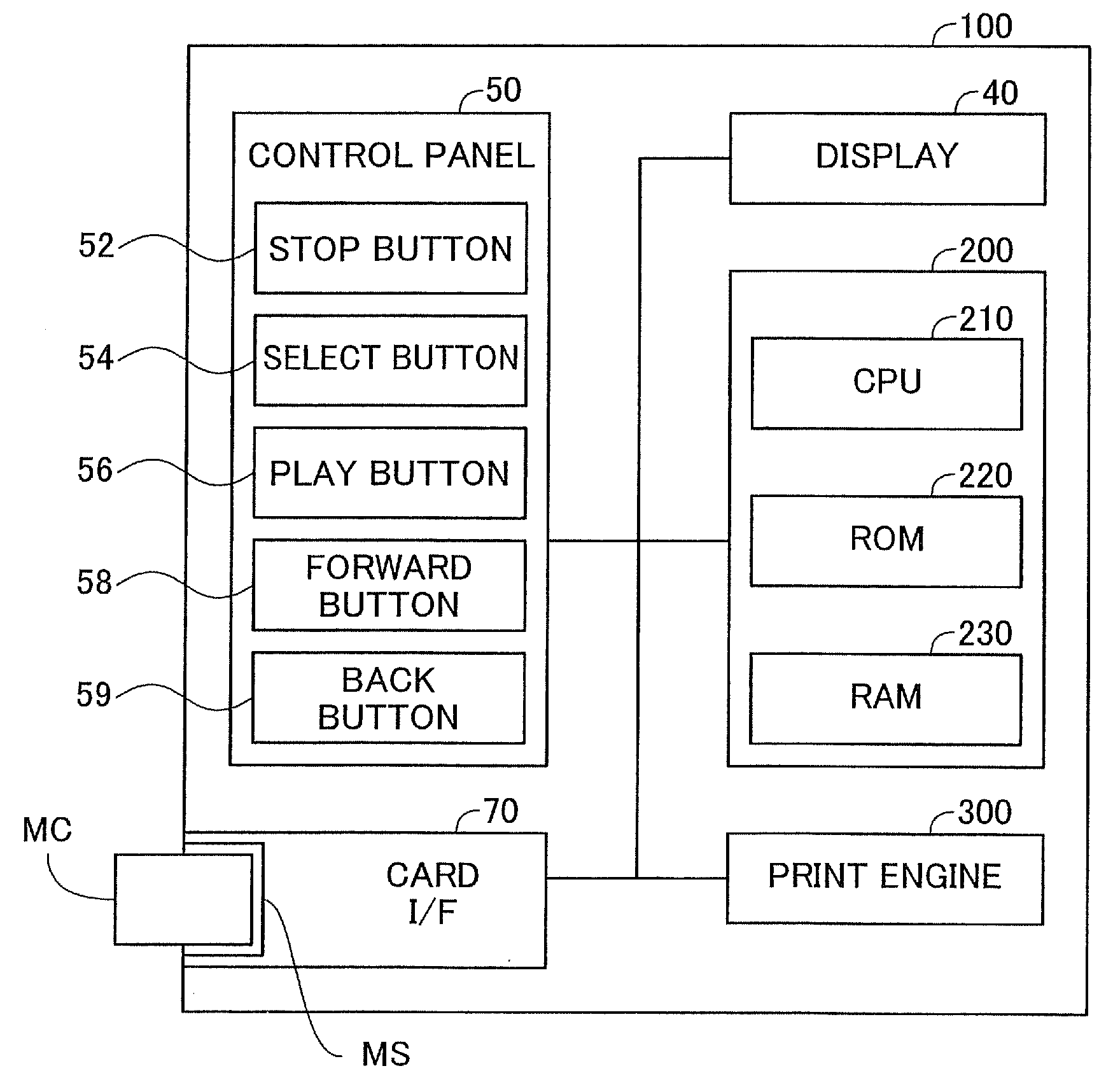
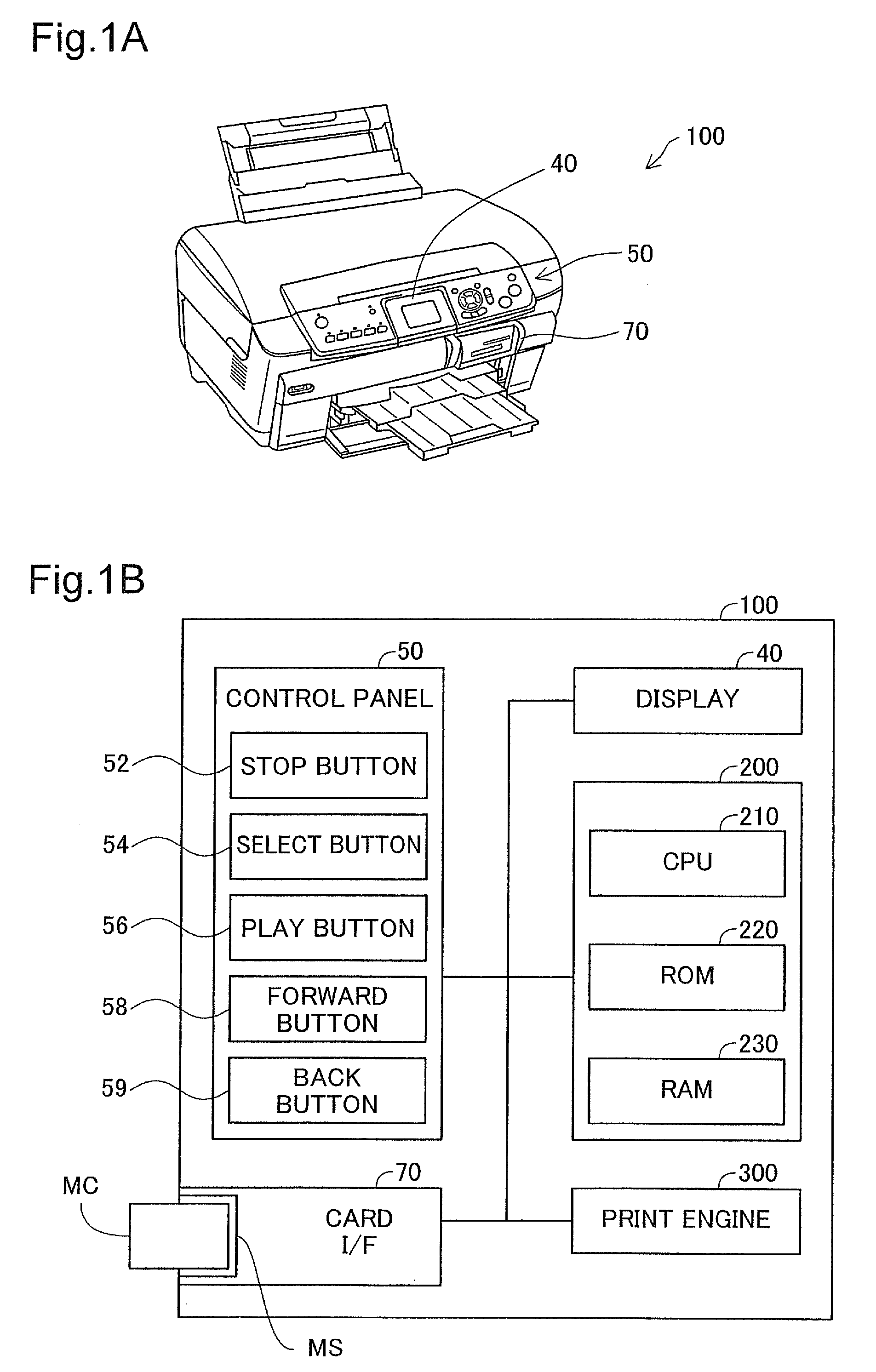
[0040]FIGS. 1A and 1B are illustrations depicting a printer according to an embodiment of the present invention. FIG. 1A depicts the exterior of a printer 100; FIG. 1B is a simplified depiction of the configuration of the printer 100. As depicted in FIG. 1A, this printer 100 includes a display 40, a control panel 50, and a memory card interface 70. As depicted in FIG. 1B, the printer 100 further includes a controller 200 and a print engine 300.

[0041]The controller 200 is a computer that includes a CPU 210, a ROM 220, and a RAM 230. This controller 200 controls the various constituent elements of the printer 100. The print engine 300 constitutes a printing mechanism for carrying out printing according to print data provided to it. As the printing mechanism, it would be possible to employ various printing mechanisms su...

embodiment 2

B. Embodiment 2

[0089]FIG. 14 is an illustration depicting an overview of another embodiment of the smoothing process. The only difference from the embodiment depicted in FIG. 13 is that the magnitude of smoothing becomes stronger as the pixel position within a pixel block become closer to the boundary line. The device configuration and process steps are the same as in the embodiment illustrated in FIGS. 1A-1B to 4, and FIG. 6.

[0090]The drawing depicts an example of a smoothing level matrix SL. This 8*8 matrix SL indicates a smoothing level at each pixel position within a pixel block. In the example of FIG. 14, the level is set to any of levels 1 to 4. Higher levels mean stronger smoothing. Also, the level is set to a greater value with decreasing distance from the boundary line Bn, Be, Bs, Bw of the pixel block.

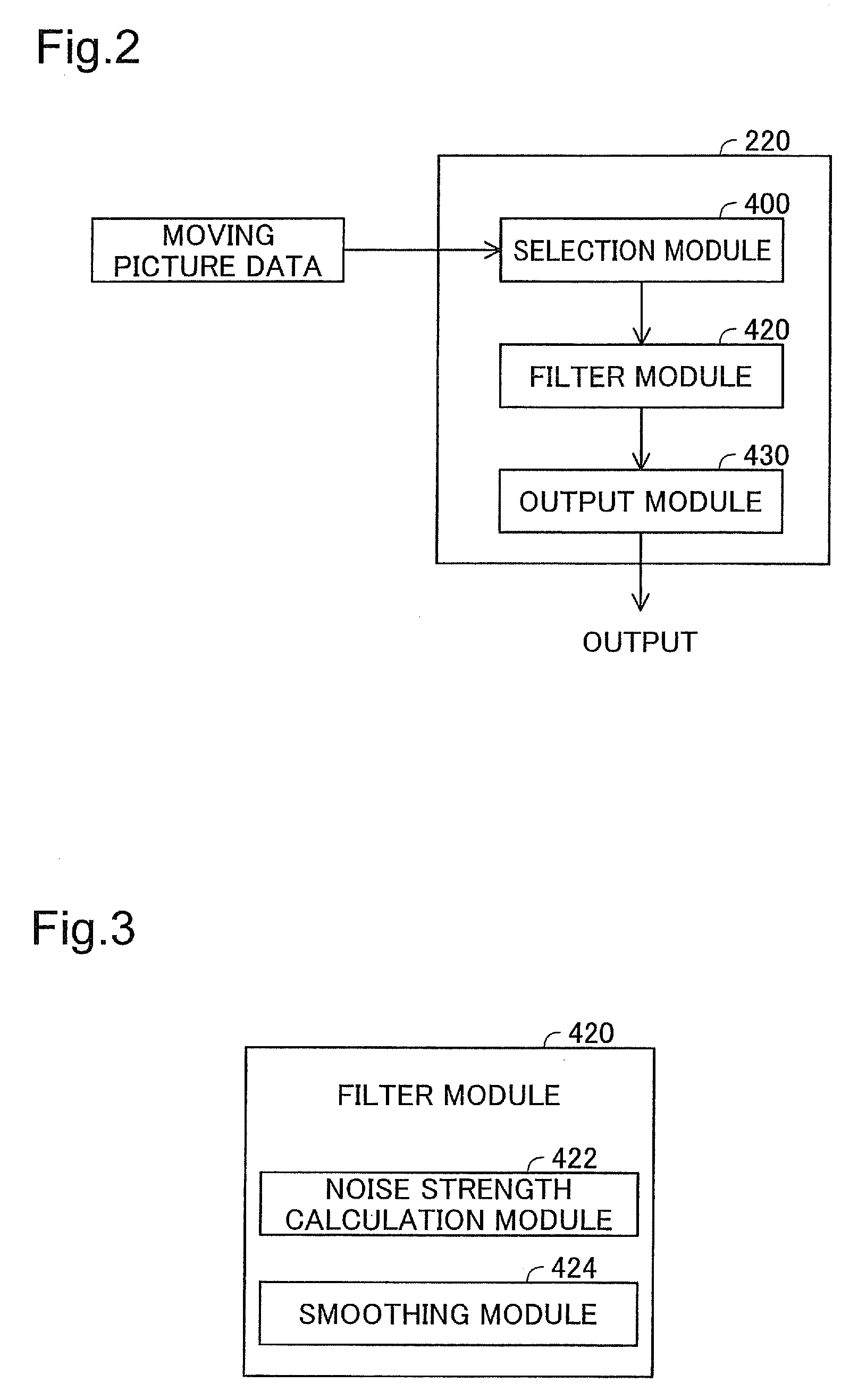
[0091]The drawing depicts the target image SI and the pixel block group BG similar to those in FIG. 7. The smoothing module 424 (FIG. 3) determines a representative normalize...

embodiment 3

C. Embodiment 3

[0095]FIG. 15 is an illustration depicting an overview of yet another embodiment of the smoothing process. The only difference from the embodiment depicted in FIG. 13 is that the normalized strength calculated through interpolation depending on pixel position within the pixel block is used in place of the representative normalized strength αf The device configuration and process steps are the same as in the embodiment illustrated in FIGS. 1A-1B to 4, and FIG. 6.

[0096]FIG. 15 depicts an overview of the smoothing process of a given target pixel PXx. In this embodiment, the smoothing module 424 (FIG. 3) calculates a horizontal normalized strength αph1 through linear interpolation of the horizontal direction hr, and a vertical normalized strength αpv1 through linear interpolation of the vertical direction vt.

[0097]The horizontal normalized strength αph1 is calculated from the left normalized strength αw of the left boundary line Bw, and the right normalized strength αe of...


PUM


Abstract

In a case where an index indicating the magnitude of the variation rate of pixel values within a target pixel block is greater than an index threshold value, weaker block noise strength is calculated compared with a case where the index is smaller than the index threshold value; and in a case where the calculated block noise strength is greater than a strength threshold value, a stronger smoothing process is carried out compared with a case where block noise strength is less than the strength threshold value.

Description

CROSS-REFERENCE TO RELATED APPLICATIONS[0001]The present application claims the priority based on Japanese Patent Application No. 2007-209654 filed on Aug. 10, 2007, the disclosure of which is hereby incorporated by reference in its entirety.BACKGROUND[0002]1. Technical Field[0003]The present invention relates to an apparatus, a method, and a program product for image processing.[0004]2. Description of the Related Art[0005]Techniques that involve splitting an image into multiple blocks for encoding are known (e.g. the JPEG format or the MPEG format). The image data is recovered from this encoded data by decoding each individual block. Non-reversible processes are one known type of encoding-decoding process of this kind (e.g. non-reversible compression-expansion). In some instances, non-reversible processes of this kind may give rise to block noise in the decoded image data (also called “block distortion”). Various processes have been proposed to reduce such block noise.[0006]However...

Claims


Application Information

Patent Timeline
IPC IPC(8): G06K9/40
CPCG06T5/002G06T2207/20192G06T2207/20021G06T2207/20012G06T5/70
Inventor SHIRAISHI, SHINICHI
Owner SEIKO EPSON CORP
Why Eureka
Try Eureka