Transflective electrowetting display device

a technology of electrowetting display and transparent coating, which is applied in the direction of display means, identification means, instruments, etc., can solve the problems of high manufacturing cost and very yield sensitive steps, and achieve the effect of improving the predictability of the motion of the second fluid and improving the uniformity of grey levels

Inactive Publication Date: 2009-11-19
LIQUAVISTA BV
View PDF8 Cites 39 Cited by
  • Summary
  • Abstract
  • Description
  • Claims
  • Application Information

AI Technical Summary

Benefits of technology

[0007]The structured reflector adds hardly any or no additional cost to the display manufacturing process as compared to the reflector for a reflective-only display device. The desired overall reflection and transmission can be achieved by choosing the relative sizes of the transparent and reflective areas.
[0010]In a preferred embodiment the cross-section of the electrowetting cell has a rectangular shape and the transparent or reflective area is an elongate area having its longest dimension in the direction of a diagonal of the rectangular shape. A rectangle is defined as a rectilinear four-sided figure having all its angles right angles. The square is a species of the rectangle. The reflective area need not be an uninterrupted area but can be two areas separated by the elongate area. The elongate area may be transparent and surrounded by a reflective area or it may be reflective and surrounded by a transparent area. Motion of the second fluid along a diagonal of a rectangular cross-section can be accurately controlled. Hence, the arrangement of the transparent or reflective area along the diagonal allows an accurate control of the grey level.
[0013]An advantage of the perforated pattern is that the grey scale is less dependent on the precise motion of the second liquid, both on the curvature of the borderline, on the position where the motion is initiated and on the position where the second liquid contracts to. This embodiment provides a great freedom for designing the motion of the second fluid.
[0015]The electrowetting element comprises preferably an initiator for controlling the direction of the motion of the second fluid. The initiator can be a special shape of hydrophobic surfaces and / or of the cross-section of the electrowetting element. The presence of an initiator realizes an improved predictability of the motion of the second fluid, thereby improving uniformity of grey levels over the image of the display device.

Problems solved by technology

A disadvantage of the known transflective display is that the partially transmissive layer requires a special step in the manufacturing process and is therefore relatively expensive to make.
As a result, this manufacturing step will be a very yield sensitive step.

Method used


Image

  • Transflective electrowetting display device
  • Transflective electrowetting display device
  • Transflective electrowetting display device

Examples


first embodiment

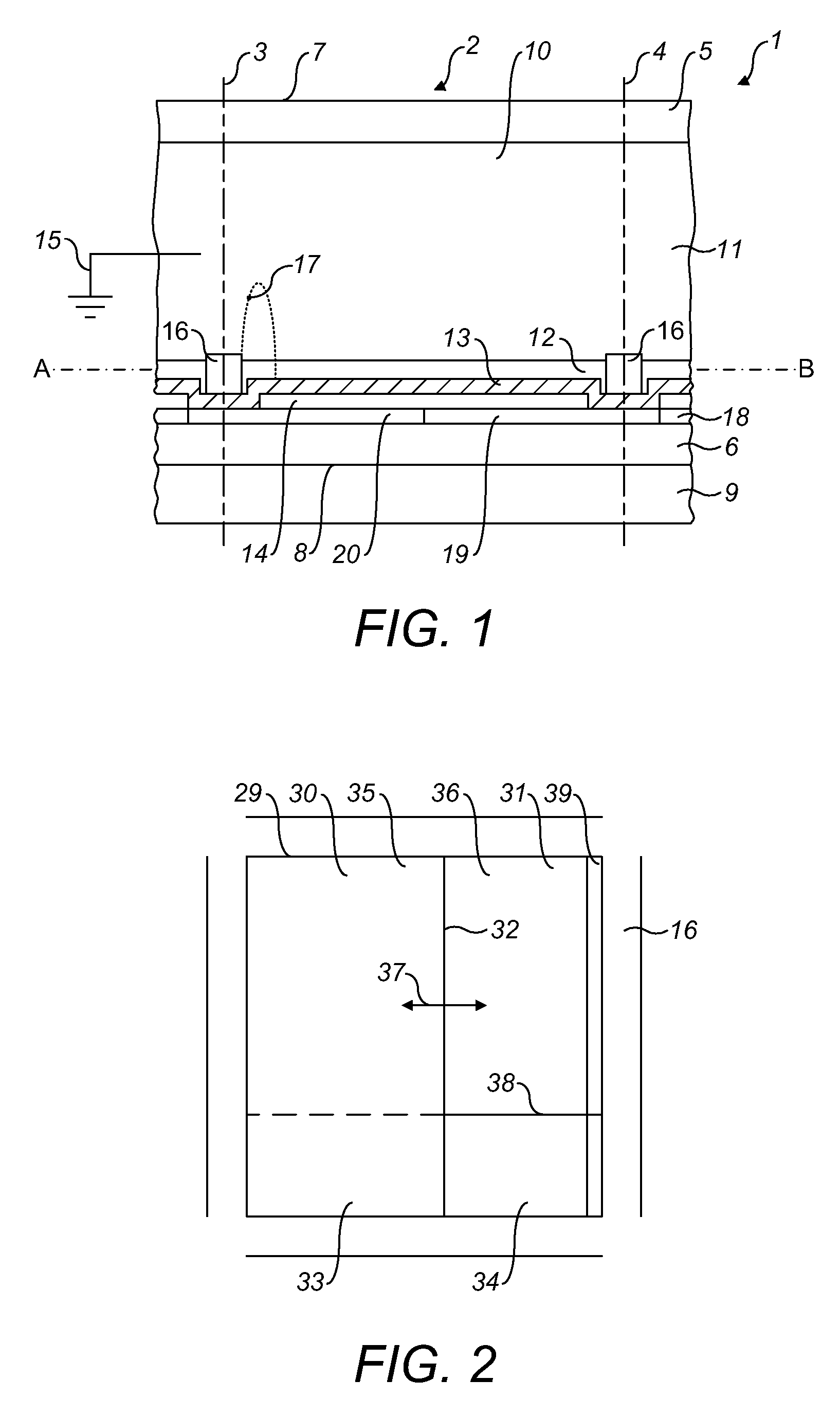
[0041]FIG. 2 shows a cross-section 29 of the space 1 of the electrowetting element 2 along the line A-B in FIG. 1 as seen from the viewing side. The second liquid covers a predetermined area 30 of the cross-section. A borderline between the predetermined area 30 and the area 31 of the cross-section not covered by the second liquid is indicated by numeral 32. The transparent area of the structured reflector is now divided in an area 33 covered by the second liquid and an area 34 not covered by the second liquid. Similarly, the reflective area of the structured reflector is divided in an area 35 covered by the second liquid and an area 36 not covered by the second liquid. The control of the position of the second liquid can move the borderline 32 in a direction 37. Although the Figures show the borderline 32 as a straight line, it may also be a curved line. The curvature is preferably mirror symmetric around the direction of motion. In the position shown in the Figure, the area 30 cov...

second embodiment

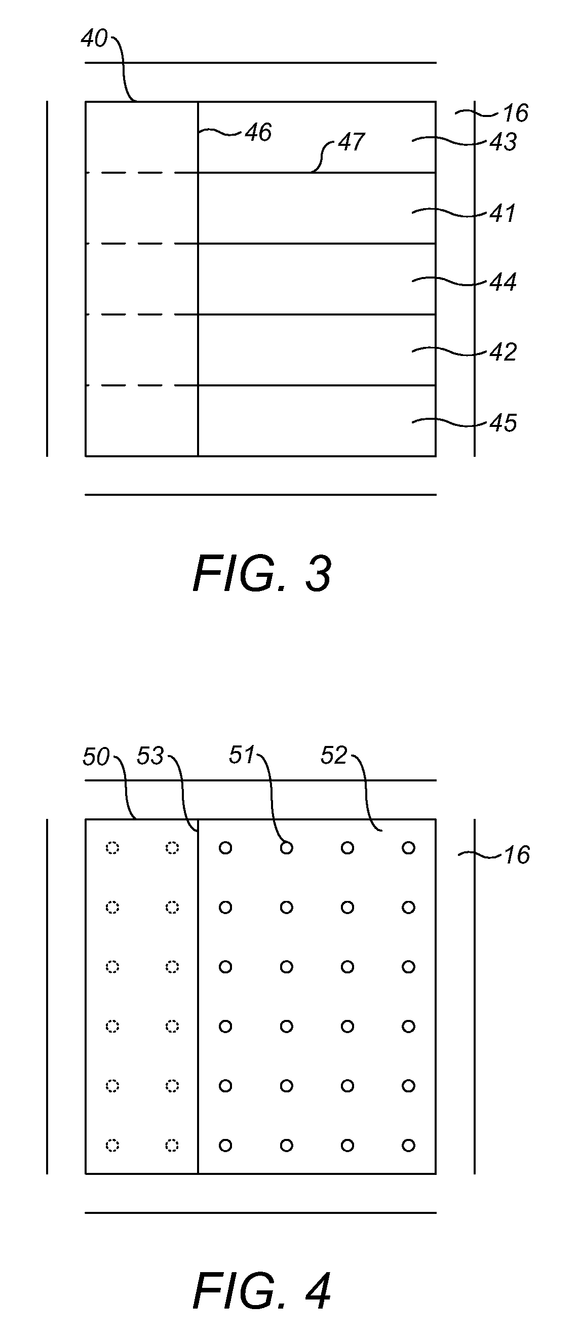
[0043]FIG. 3 shows a cross-section 40 of the electrowetting element as seen from the viewing side. The structured reflector comprises a plurality of transparent and reflective areas: two transparent areas 41, 42 and three reflective areas 43, 44, 45. In the state of the electrowetting element shown, the second liquid covers the area of the cross-section to the left of the borderline 46. Similar to FIG. 2, the parts of the dividing lines between the transparent areas and the reflective areas that are covered by the second liquid are shown as dashed lines. When the borderline moves in a direction parallel to the dividing line 47 between the reflective area 43 and the transparent area 41, the proportions of the transparent areas and the reflective areas covered by the second liquid remain substantially equal.

third embodiment

[0044]FIG. 4 shows a cross-section 50 of the electrowetting element as seen from the viewing side. The structured reflector comprises a plurality of transparent areas 51, each of which is enclosed by a reflective area 52. The transparent areas may be arranged in the form of a regular array as shown in the Figure. Alternatively, the transparent areas may be arranged randomly within the cross-section. The part of the cross-section on the left of borderline 53 is covered by the second liquid. The number of transparent areas in the cross-section may be chosen in dependence on the desired behaviour of the grey level as a function of the position of the borderline 53. When the number of transparent areas becomes larger, the dependence of the grey level on the position of the borderline will better approximate a linear function. In this embodiment the proportions of transparent areas and reflective area covered by the second liquid is substantially independent of the direction of motion of...


PUM


Abstract

A transflective display device has a viewing side (7) and a rear side (8) and comprises a plurality of electrowetting elements (2) having a first support plate (5) facing the viewing side and a second support plate (6) facing the rear side. Each electrowetting element comprises a space (10) between the first support plate and the second support plate and includes a first fluid (11) and a second fluid (12) immiscible with each other. The second fluid absorbs at least a part of the optical spectrum. The position of the second fluid is controllable to cover a predetermined area (30) of the cross-section (29) of the space in the plane of the second support plate. A structured reflector (18) is arranged on the second support plate, comprising within the cross-section an area (33, 34) transparent for light incident from the rear side and an area (35, 36) reflective for light incident from the viewing side. The transparent area and the reflective area are arranged such that the predetermined area (30) covered by the second fluid covers the same proportion of the transparent area and the reflective area.

Description

FIELD OF THE INVENTION[0001]The invention relates to a transflective electrowetting display comprising a plurality of electrowetting elements having a first support plate facing a viewing side of the display and a second support plate facing a rear side of the display. A transflective display can form an image in a reflective mode using front lighting, e.g. by ambient light, and in a transmissive mode, using back lighting.BACKGROUND OF THE INVENTION[0002]A transflective electrowetting display is disclosed in international patent application WO2006 / 017129. This known display includes electrowetting elements having a partially, uniformly transmissive layer arranged on the second support plate. In a first mode the layer reflects ambient light incident from the viewing side and in a second mode it transmits light incident from the rear side. Each electrowetting element comprises a transparent liquid and a black or coloured liquid. The position of the latter liquid in the electrowetting ...

Claims


Application Information

Patent Timeline
Patent Type & Authority Applications(United States)
IPC IPC(8): G02B26/02
CPCG02B26/004G09F13/16G09F9/372G09G3/3433G02B26/005
Inventor FEENSTRA, BOKKE JOHANNESVAN DIJK, ROYGIRALDO, ANDREAHAYES, ROBERT A.
Owner LIQUAVISTA BV
Why Eureka
Try Eureka