Data transmitting system, data transmitting method, base station and mobile station

a data transmission and data technology, applied in the field of radio communication, can solve the problems of reducing the radio efficiency of the common channel, and complicated processes until the ue starts to receive mbms content, and achieve the effect of simple procedure without reducing the radio efficiency of the shared radio channel

Inactive Publication Date: 2009-11-19
NTT DOCOMO INC
View PDF5 Cites 21 Cited by
  • Summary
  • Abstract
  • Description
  • Claims
  • Application Information

AI Technical Summary

Benefits of technology

[0010]According to one or more embodiments of the present invention, the MBMS content can be tran

Problems solved by technology

As mentioned above, according to the conventional method, the processes performed until the UE starts to receive MBMS content are complicated.
In addition, it may decrease radio efficiency of the common channel to uniformly transmit the control information periodically over the SCC

Method used


Image

  • Data transmitting system, data transmitting method, base station and mobile station
  • Data transmitting system, data transmitting method, base station and mobile station
  • Data transmitting system, data transmitting method, base station and mobile station

Examples


embodiment 1

[0047]In the following, a first embodiment of the present invention is described.

[0048]

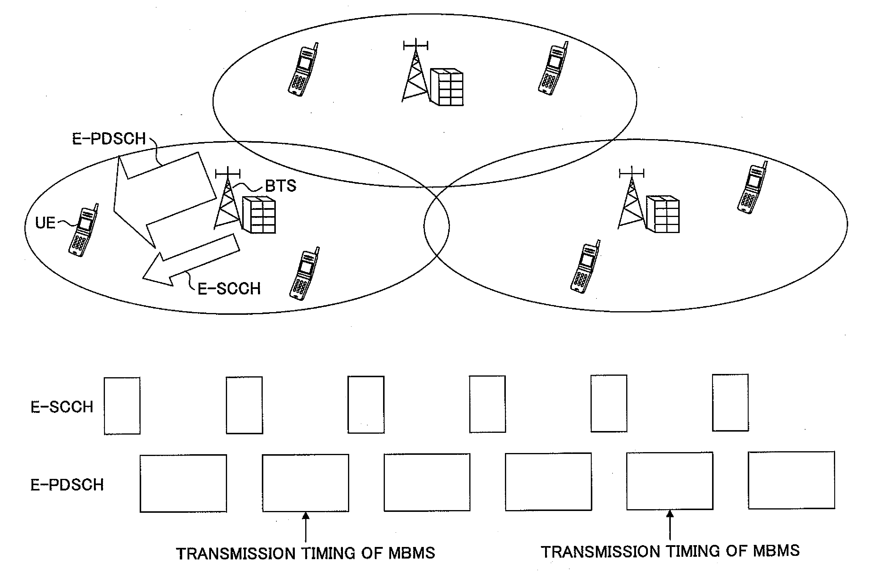
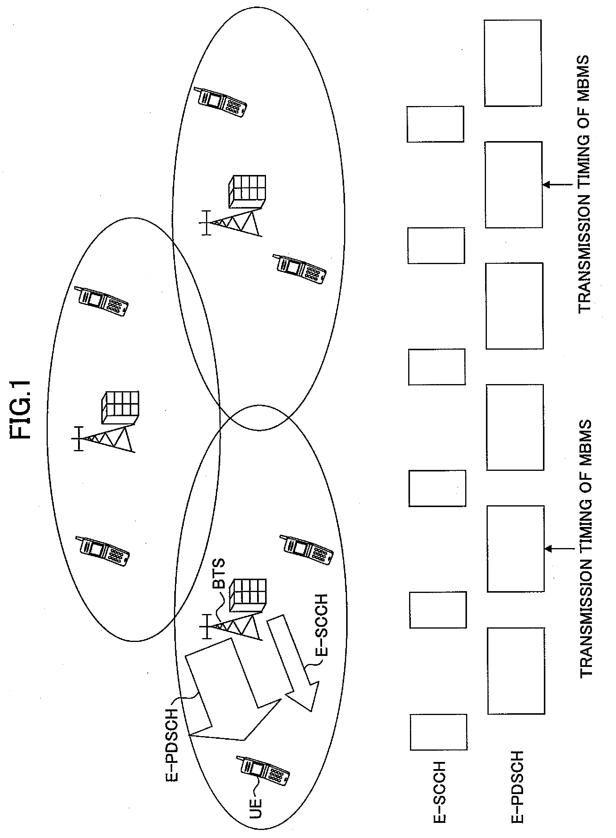
[0049]FIG. 1 shows a communication system in the present embodiment. FIG. 1 shows a plurality of radio base stations (BTS) and a plurality of mobile stations (UE). The base stations are connected to an upper apparatus. As the upper apparatus, a router and a broadcast multicast service center (BM-SC) and the like may be included. However, the apparatuses and a core network and the like are not shown for the sake of simplicity of representation of the figure. A shared radio physical channel (E-PDSCH) that can transmit MBMS content, and a shared associated control channel (E-SCCH) associated with the shared radio physical channel are prepared between the BTS and the UE, E-SCCH can transmit an associated control signal for MBMS content multicasting. Usage of the E-PDSCH and the E-SCCH is not limited to MBMS, and they may be used for various usages. Transmission of the MBMS content may be called multic...

embodiment 2

[0078]In the second embodiment of the present invention, same MBMS contents that are transmitted from a cell (serving cell) where a UE is currently residing and from an adjacent cell (non serving cell) are combined. In the present embodiment, it is desirable that a plurality of base stations are synchronized with each other in terms of time. The radio transmission unit 22 of the UE used in the present embodiment includes a function for causing a plurality of descramble and demodulation functions to operate at the same time such that the UE can receive a plurality of E-SCCHs transmitted from adjacent cells at the same time. The “cell” of the present embodiment may be defined to include a plurality of “sectors.” Alternatively, “cell” may be used to mean the same meaning as “sector.” In any cases, the present invention can be used. In the following description, “cell” and “sector” are used synonymously as a matter of convenience.

[0079]The UE identifies a cell (other cell), other than t...


PUM


Abstract

A data transmission system is disclosed for multicasting user common data from one or more radio base stations to one or more mobile stations. The radio base station is configured to transmit user common data using a shared data channel, transmit associated control information using an associated control channel, and transmit broadcast information using a broadcast channel. The mobile station is configured to receive the shared data channel, the associated control channel and the broadcast channel. The mobile station is further configured to analyze the broadcast information and the associated control information. The broadcast information includes information indicating transmission timing of the associated control channel. The associated control information includes information of a radio parameter of the shared data channel and includes distribution information indicating multicasting time of the user common data.

Description

TECHNICAL FIELD[0001]The present invention relates to radio communication. More particularly, the present invention relates to a data transmission system, a data transmission method, a base station and a mobile station for transmitting a signal for Multimedia Broadcast / Multicast Service (MBMS).BACKGROUND OF THE INVENTION[0002]In mobile communication systems in recent years, in addition to voice services of a circuit switching type, large capacity multimedia services based on a packet switching scheme are starting to be provided. In the 3GPP (3rd generation partnership project), MBMS is assumed to be used in the packet switching scheme, so that configurations of UTRAN architecture and radio channels related to MBMS are disclosed (refer to non-patent document 1). Content of the MBMS is represented by a traffic channel (MTCH), and control channels (MCCH and MSCH) for transmitting it are transmitted over SCCPCH (Secondly Common Control Physical Channel). MCCH includes control messages s...

Claims


Application Information

Patent Timeline
IPC IPC(8): H04H20/71H04W4/06
CPCH04W72/005H04B7/2637
Inventor MOTEGI, MASAYUKIKATO, YASUHIROISHII, MINAMINAKAMURA, TAKEHIRO
Owner NTT DOCOMO INC
Why Eureka
Try Eureka