
Method for operating a chemical deposition chamber

Active Publication Date: 2009-11-19
UNITED MICROELECTRONICS CORP
View PDF10 Cites 1 Cited by
  • Summary
  • Abstract
  • Description
  • Claims
  • Application Information

AI Technical Summary

Benefits of technology

[0012]The present invention therefore provides a novel method for operating a chemical deposition chamber, which is characterized in that the flow rate of the

Problems solved by technology

Moreover, the deposition rate of the film is another factor, because it affects the throughput of the deposition chamber and a high deposition rate often compromise with the quality of the films.
In addition, the materials from the precursors by chemical reactions not only uniformly deposit on the substrate but also accumulate on the inner walls of the chemical deposition chamber to cause contamination along with by-products.
Such materials and by-products accumulated on the inner walls of the chemical deposition chamber on one hand cause the source of contaminations such as particles or peelings, but also affect the thermal conductivity of the chemical deposition chamber.
However, the inventor obs

Method used


Image

  • Method for operating a chemical deposition chamber
  • Method for operating a chemical deposition chamber

Examples


Example

[0016]The present invention provides a novel method for operating a chemical deposition chamber. The method of the present invention is characterized in that a pre-tuning step is performed on the digital liquid flow controller after the chamber-cleaning step so that the flow rate of the precursor fluid is able to be stabilized by a simple way as soon as possible. After that, the material layers obtained from the deposition procedure in the chemical deposition chamber may have uniform thickness because of the stabilized flow rate of the precursor fluid. The method of the present invention is simple and fast, and may greatly boost the efficiency of the chemical deposition step.

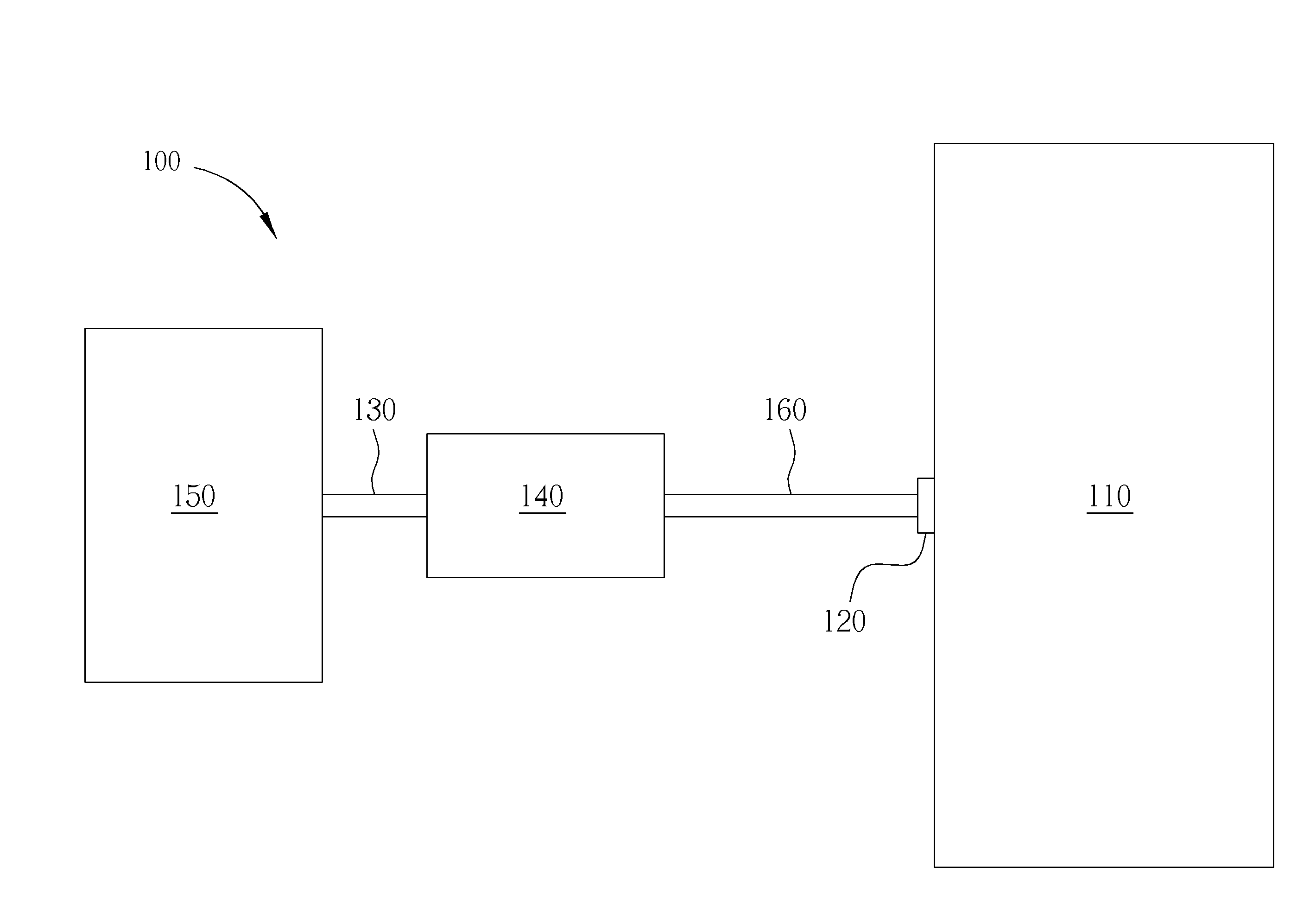
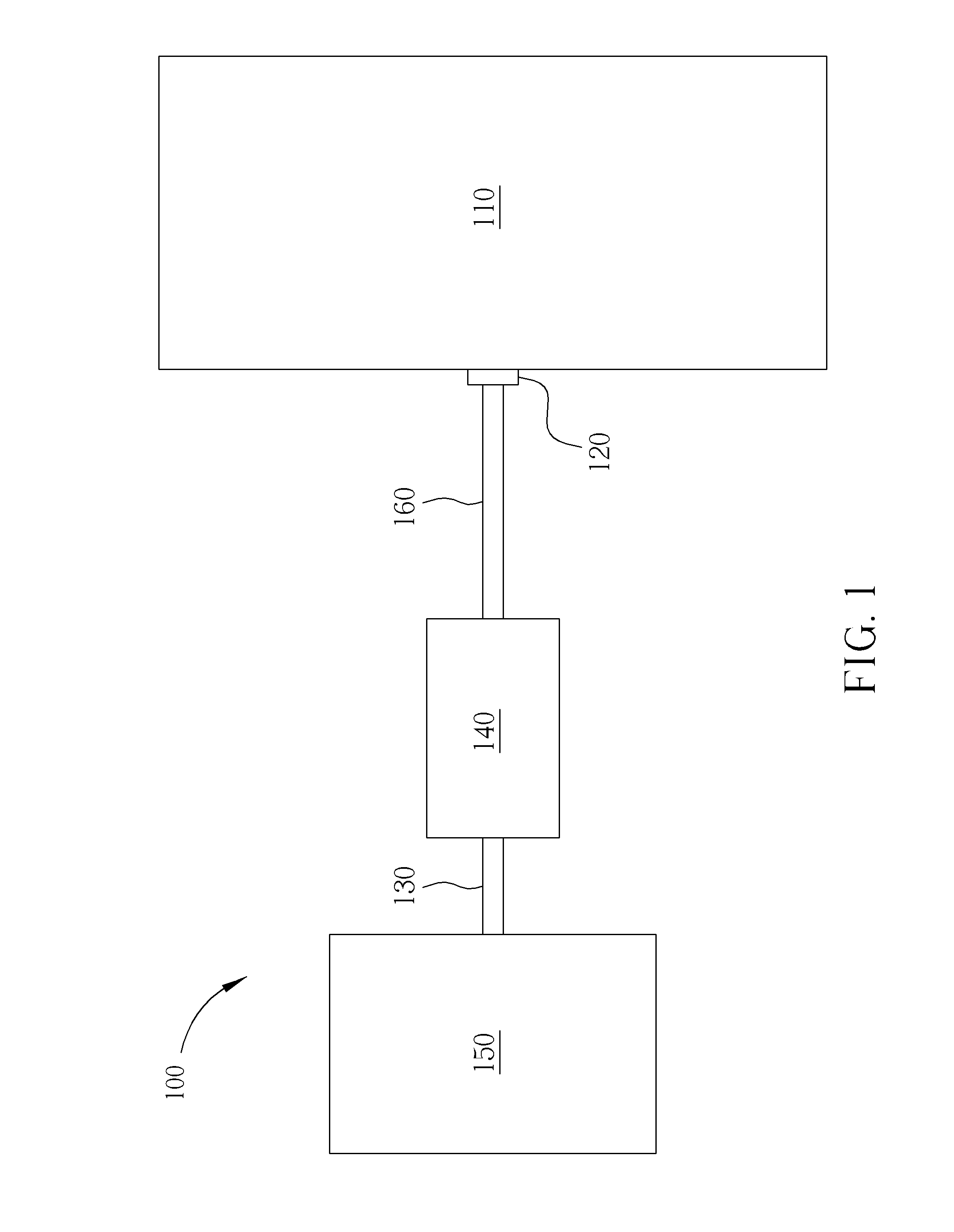
[0017]FIG. 1 illustrates a preferred embodiment of the method for operating a chemical deposition chamber of the present invention. First, a chemical vapor deposition system 100 is provided. The chemical vapor deposition system 100 includes a chemical deposition chamber 110, a precursor inlet 120, a precursor fl...


PUM

PropertyMeasurementUnit
Timeaaaaaaaaaa
Timeaaaaaaaaaa
Flow rateaaaaaaaaaa

Abstract

A method for operating a chemical deposition chamber is disclosed. First, a digital liquid flow controller is provided to guide a precursor fluid into a chemical deposition chamber. Then, a pre-cleaning step is performed in the chemical deposition chamber. Later, a pre-tuning step is performed on the digital liquid flow controller so that the precursor fluid can be substantially stably guided into the chemical deposition chamber. Afterwards, the chemical deposition chamber is used to carry out the chemical deposition.

Description

BACKGROUND OF THE INVENTION [0001]1. Field of the Invention[0002]The present invention relates to a method for operating a chemical deposition chamber. In particular, the present invention relates to a method for operating a chemical deposition chamber so that a precursor fluid can be substantially stably guided into the chemical deposition chamber.[0003]2. Description of the Prior Art[0004]The method of chemical vapor deposition plays an important role in the manufacturing of the semiconductors. The chemical vapor deposition enables the construction and development of a solid film from various specific materials on a wafer, such as poly-Si layers, interlayer dielectrics, interlayer metal dielectrics, shallow trench isolations and passivations in a range from as low as 0.5 μm to several μm. The desirous elements or material layers are therefore formed on the wafers with the help of appropriate lithographic or etching procedures.[0005]The general chemical vapor deposition system usua...

Claims


Application Information

Patent Timeline
IPC IPC(8): C23C16/44
CPCC23C16/455
Inventor LAI, CHIEN-HSINTSENG, TZU-CHINCHANG, YING-YI
Owner UNITED MICROELECTRONICS CORP
Learn More