
System and method for improving efficiency of turbine airfoils

Inactive Publication Date: 2017-01-26
WINNOVA ENERGY LLC
View PDF44 Cites 4 Cited by
  • Summary
  • Abstract
  • Description
  • Claims
  • Application Information

AI Technical Summary

Benefits of technology

The patent describes systems and methods to improve the aerodynamic efficiency and reliability of airfoils by designing new blade profiles that generate greater lifting force and reduce drag force. The new blade profiles also generate a counter force in the opposite direction of drag force, which increases efficiency and reduces strain on the rotor and blades. These two aspects are combined to synergistically boost the efficiency of the airfoil.

Problems solved by technology

In practical designs, inefficiencies in the design and frictional losses will reduce the power available from the wind still further.
Converting this wind power into electrical power also incurs losses of up to 10% in the drive train and the generator and another 10% in the inverter and cabling.
Furthermore, when the wind speed exceeds the rated wind speed, control systems limit the energy conversion in order to protect the electric generator so that ultimately, the wind turbine will convert only about 30% to 35% of the available wind energy into electrical energy.
While using rotors with multiple blades should capture more wind energy, there is a practical limit to the number of blades which can be used because each blade of a spinning rotor leaves turbulence in its wake, which reduces the amount of energy the following blade can extract from the wind.
This same turbulence effect also limits the possible rotor speeds because a high speed rotor does not provide enough time for the air flow to settle after the passage of a blade before the next blade comes along.
With too few rotor blades, or a slow turning rotor, most of the wind will pass undisturbed through the gap between the blades reducing the potential for capturing the wind energy.
This can be a disadvantage as it limits the areas in which a turbine can be placed to those with relatively high average wind speed.
There are numerous variations on single profile designs, however the art does not teach two blade profiles physically coupled together.
This increases the torque of the blade.

Method used


Image

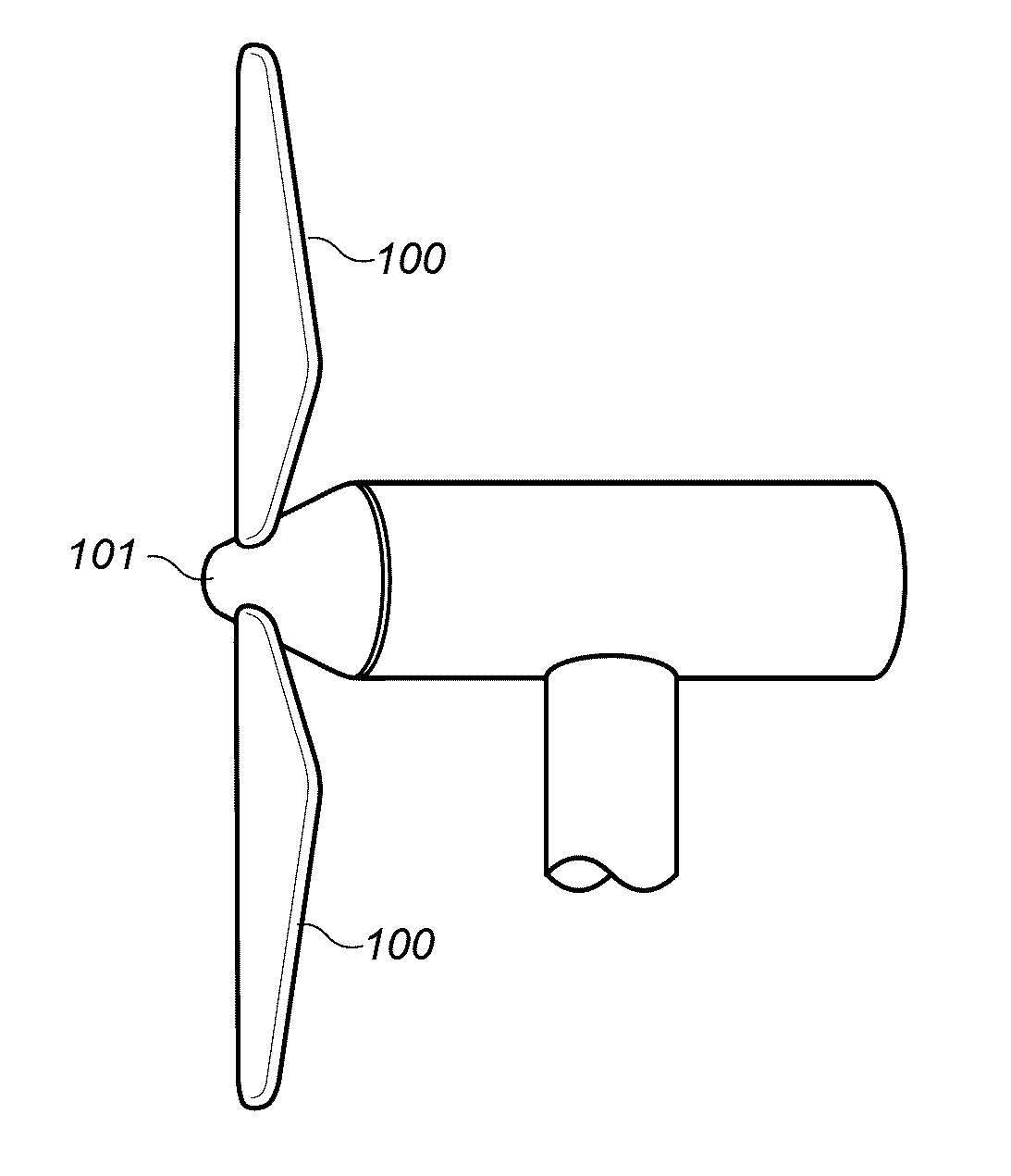
  • System and method for improving efficiency of turbine airfoils
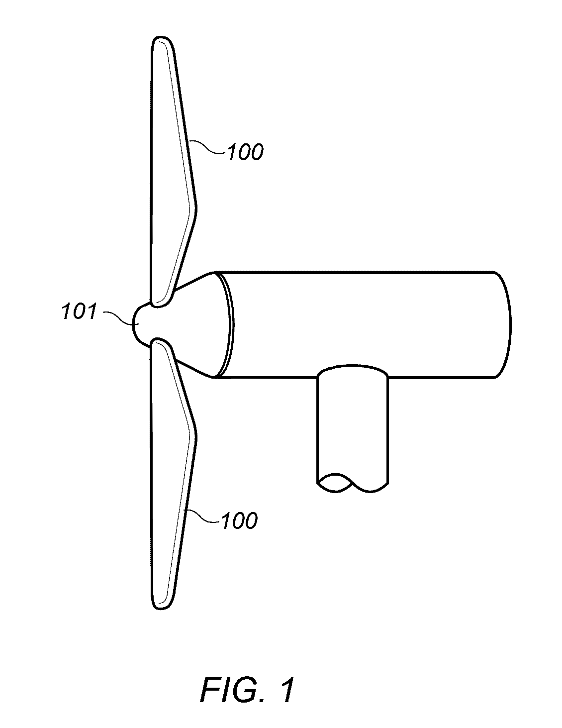
  • System and method for improving efficiency of turbine airfoils
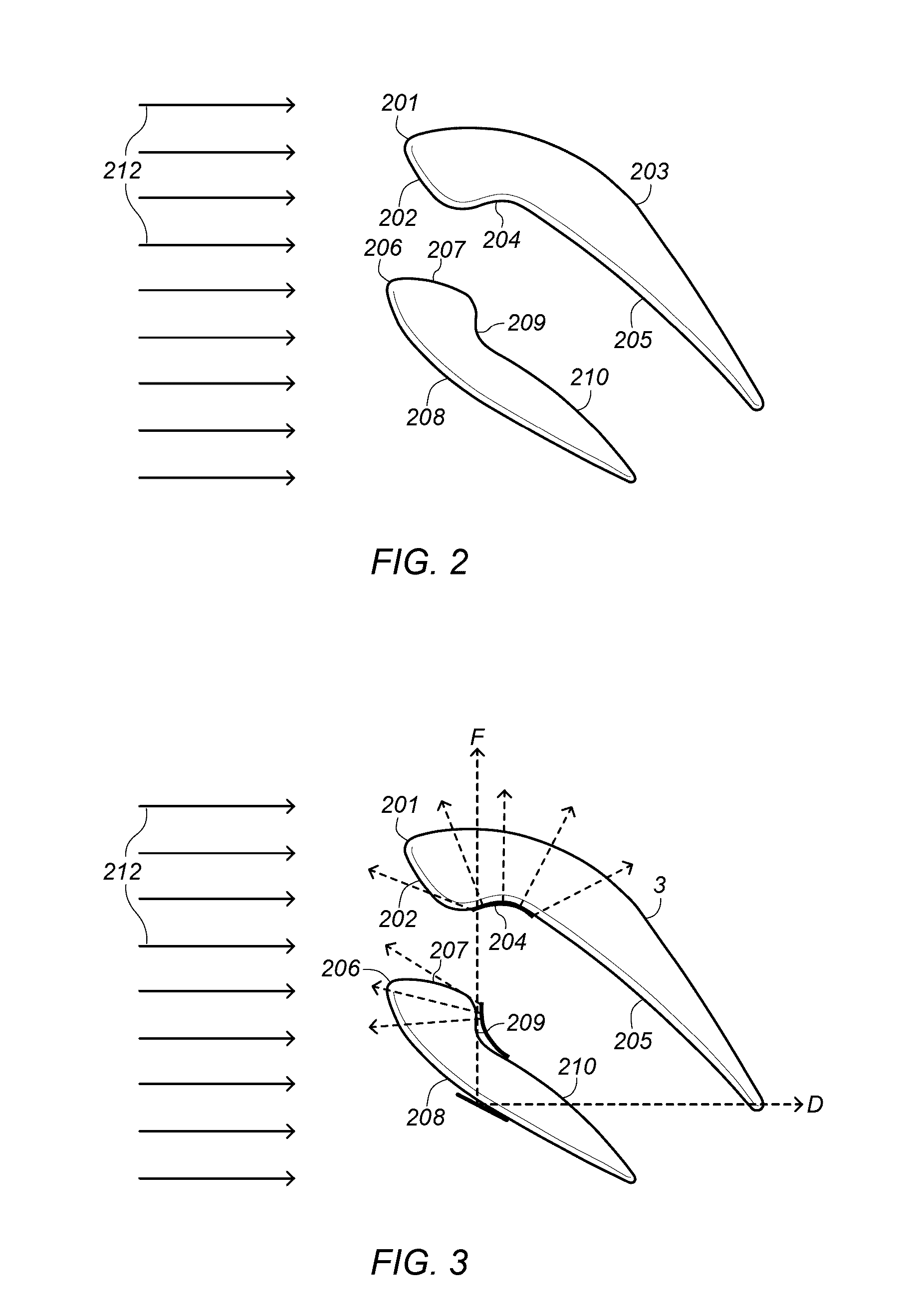
  • System and method for improving efficiency of turbine airfoils

Examples


Embodiment Construction

[0034]This specification includes references to “one embodiment” or “an embodiment.” The appearances of the phrases “in one embodiment” or “in an embodiment” do not necessarily refer to the same embodiment. Particular features, structures, or characteristics may be combined in any suitable manner consistent with this disclosure.

[0035]In the context of this patent, the term “coupled” means either a direct connection or an indirect connection (e.g., one or more intervening connections) between one or more objects or components. The phrase “directly connected” means a direct connection between objects or components such that the objects or components are connected directly to each other so that the objects or components operate in a “point of use” manner.

[0036]The lift coefficient (CL) is a dimensionless coefficient that relates the lift generated by a lifting body to the fluid density around the body, the fluid velocity and an associated reference area. A lifting body is a foil or a c...


PUM


Abstract

Double blade airfoils and related systems are disclosed. The double blade design may efficiently use a minimal amount of material yet achieve exceptional aerodynamic efficiencies well above the previously understood theoretical maximum. The disclosed designs may operate at lower wind speeds than those known in the art. Furthermore, the balance of forces generated by the disclosed designs may also reduce the stress felt by the airfoils and rotor, enhancing the longevity of the system.

Description

BACKGROUND[0001]Field of the Invention[0002]The invention relates generally to the field of wind turbines, and more specifically to improved blade designs that increase power, efficiency, and reliability. The blades may be utilized in a variety of applications, including wind turbines and turbine engines.[0003]Description of Related Art[0004]Wind turbines are an important component of renewable sources of energy generation. Wind turbine technology has been applied to large-scale power generation applications. Of the many challenges that exist in harnessing wind energy, one is maximizing wind turbine performance while ensuring reliability and broad applicability. Non-limiting examples of improved wind turbine performance parameters, which lead to minimized cost of energy, include maximized aerodynamic efficiency, maximized energy output, minimized wind turbine system loads, minimized noise, and combinations thereof.[0005]The blade profiles are the most important factor in determining...

Claims


Application Information

Patent Timeline
IPC IPC(8): F03D1/06
CPCF05B2240/231F03D1/0675F03D1/0633F05B2240/30Y02E10/72
Inventor HOKELEK, YUCEL
Owner WINNOVA ENERGY LLC
Learn More