
Air filter housing with sealing means

Inactive Publication Date: 2009-11-26
CAMFIL
View PDF19 Cites 4 Cited by
  • Summary
  • Abstract
  • Description
  • Claims
  • Application Information

AI Technical Summary

Benefits of technology

[0004]This objective is accomplished by an air filter housing having at least one filter chamber for receiving at least one filter unit, an access opening in a side wall of said housing leading to said filter chamber, a door for closing said access opening and a clamping device for holding said at least one filter unit in abutment against a first end wall of said filter chamber, characterised in that, when a filter unit is held by said clamping device, a portion of said clamping device is sealingly in abutment with a circumferential portion of the wall of said housing in the second end of said filter chamber so that air or decontamination gas that has passed through the filter unit can not enter the filter chamber outside of the filter unit. By such a construction double security against dangerous leakage through access openings to filter chambers is achieved.

Problems solved by technology

There is thus a risk that the filter unit will contain dangerous contaminations after the filtering device has been in operation.
In known filter housings of the kind mentioned in the introduction there is nothing to stop filtered air or contamination gas to reach the region in the filter chamber surrounding the circumferential side walls of the filter unit and thereby there is a risk that the outside of the filter unit will be contaminated by infectious or contagious matter that has escaped being captured in the filter unit.
However, since said region is outside the main stream of contamination gas it will take a rather long time before one can be sure that the contamination gas has reached or “leaked” into the whole of this region.
It is also a risk that contaminated air or decontamination gas will leak out of the housing if sealings between the doors for the openings giving access to the filters are defective.

Method used


Image

  • Air filter housing with sealing means
  • Air filter housing with sealing means
  • Air filter housing with sealing means

Examples


Embodiment Construction

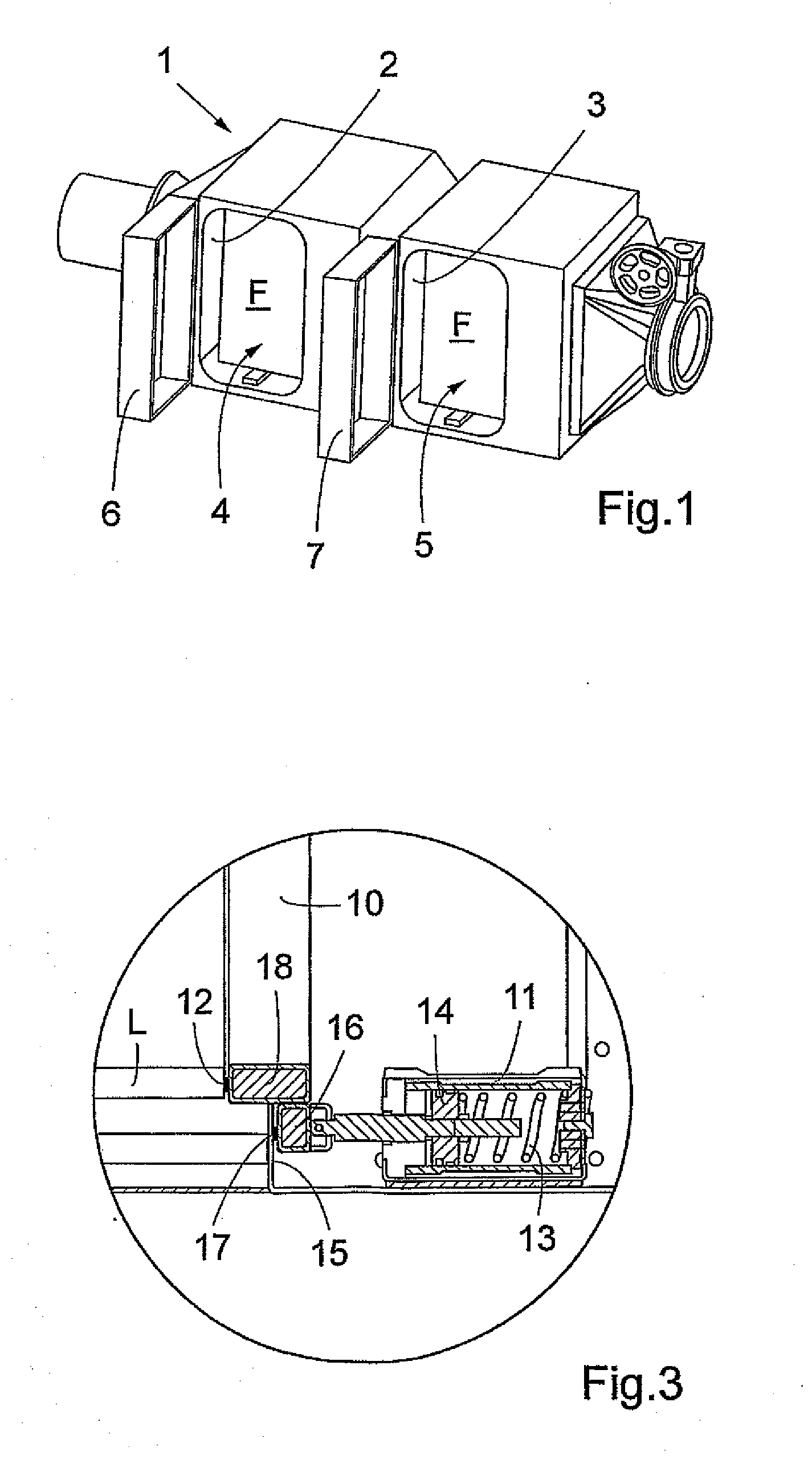
[0010]In FIG. 1, a schematic perspective view of an air filter housing 1 according to a preferred embodiment of the present invention is shown. In the preferred embodiment, the housing includes two filter chambers 2,3 in each of which an air filter unit F is disposed. Access to filter chambers 2,3 is gained by access openings 4,5. These access openings are closable by doors 6,7 shown in their open position in FIG. 1.

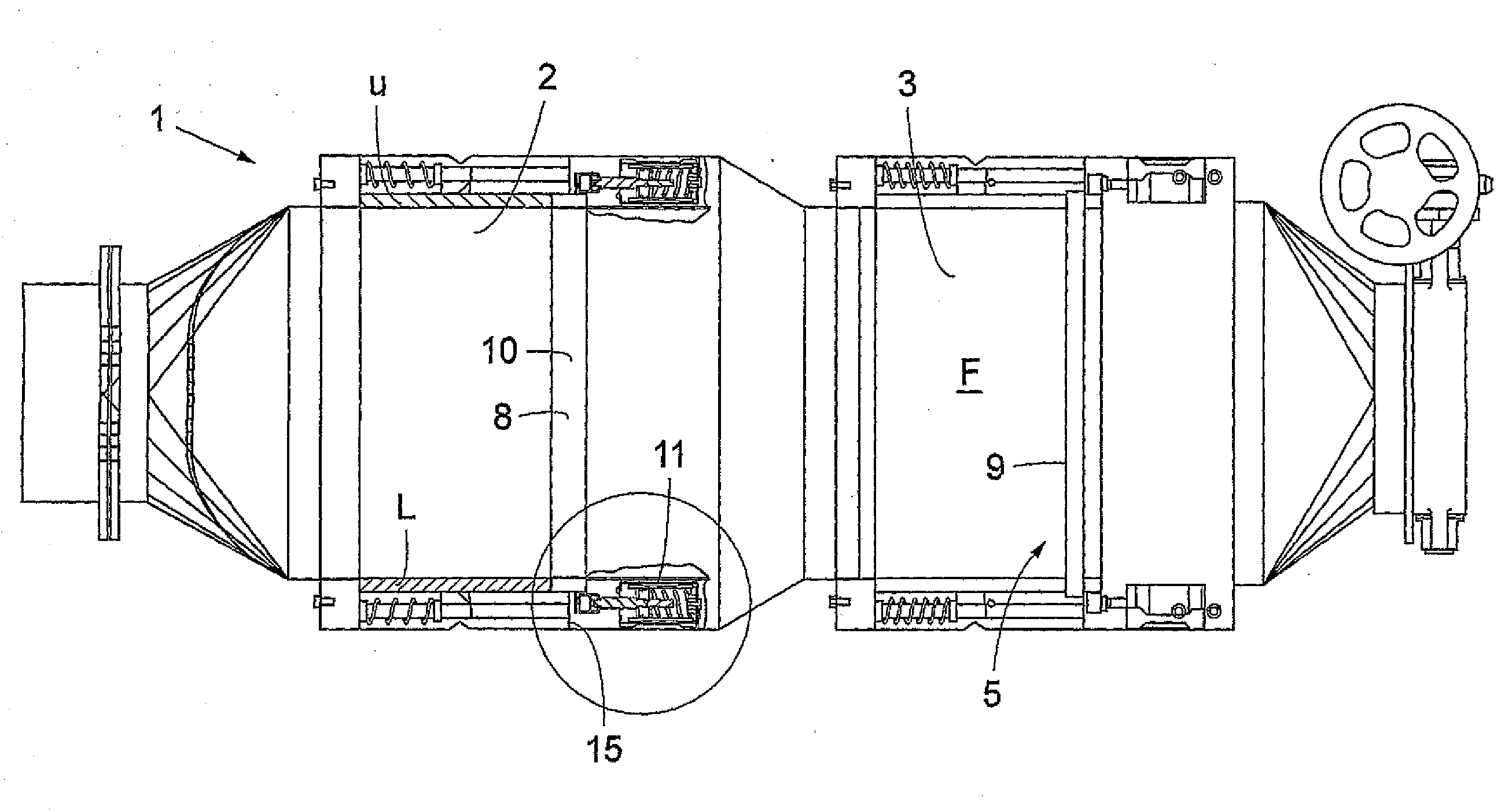
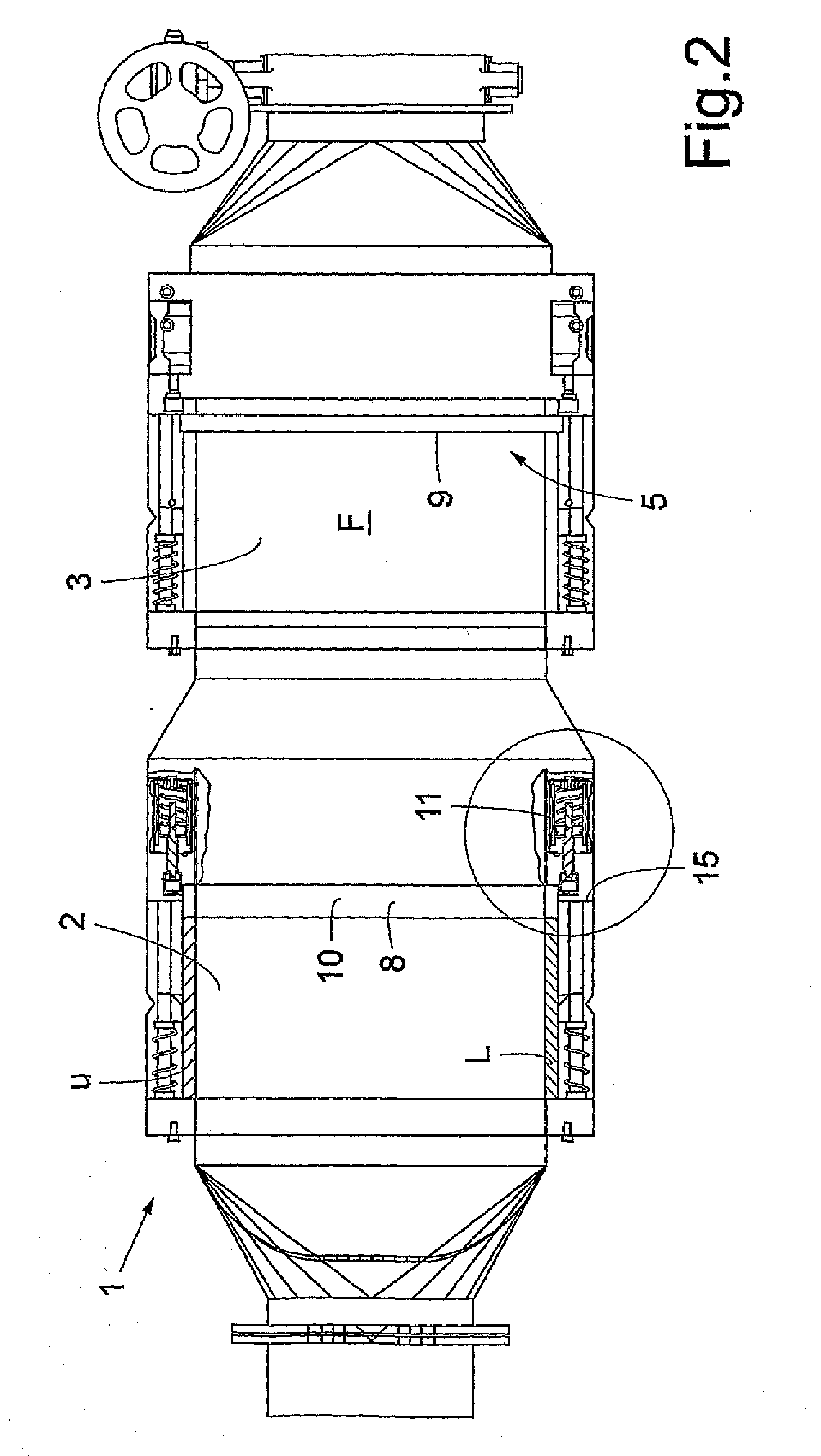
[0011]In FIG. 2, the filter housing 1 is shown in a partially sectioned plan view seen from the side of the housing 1 containing the access openings 4,5. The doors 6,7 are not shown in FIG. 2. As can be seen in FIG. 2, each filter unit F comprises a circumferential wall surrounding the filter media and ensuring that air passing through the filter unit will not sidewise leak out of the filter unit but pass through the unit from one end to the other, i.e. in the longitudinal direction of the filter housing 1. In FIG. 2 the upper U and lower part L of this circumferential w...


PUM


Abstract

An air filter housing (1) has at least one filter chamber (2, 3) for receiving at least one filter unit (F), an access opening (4, 5) in a side wall of the housing leading to the filter chamber, a door (6,7) for closing the access opening and a clamping device (10, 11) for holding the at least one filter unit in abutment against a first end wall of the filter chamber. A portion (16) of the clamping device is, when a filter unit (F) is held by the clamping device (10, 11), sealingly in abutment with a circumferential portion (15) of the wall of the housing (1) in the second end of the filter chamber (2, 3) so that air or decontamination gas that has passed through the filter unit (F) can not enter the filter chamber outside of the filter unit.

Description

TECHNICAL FIELD[0001]The present invention relates to an air filter housing having at least one filter chamber for receiving at least one filter unit, an access opening in a side wall of said housing leading to said filter chamber, a door for closing said access opening and a clamping device for holding said at least one filter unit in abutment against a first end wall of said filter chamber.BACKGROUND OF THE INVENTION[0002]Filter housings according to the introduction are known from filtering devices for certain laboratories or the like in which there is a risk that the ambient air will be contaminated. In order to prevent air from such environment to leak out, such laboratories often are set under sub-pressure. The function of the filter is to capture all infectious particles or other contaminations, such as bugs or other air carried infectious organisms, in the circulated air. There is thus a risk that the filter unit will contain dangerous contaminations after the filtering devi...

Claims


Application Information

Patent Timeline
IPC IPC(8): B01D46/10F24F8/10
CPCB01D46/0005B01D46/10F24F13/28B01D2271/02B01D2265/024
Inventor MAHLER, AXEL
Owner CAMFIL
Features
  • Generate Ideas
  • Intellectual Property
  • Life Sciences
  • Materials
  • Tech Scout
  • Unparalleled Data Quality
  • Higher Quality Content
  • 60% Fewer Hallucinations
Learn More