Apparatus, system and method for administering an anesthetic agent for a subject breathing

a technology of anesthetic agent and subject breathing, applied in the field of apparatus, a system and a method of administering anesthetic agent for a subject breathing, can solve the problems of requiring a lot of infrastructure, requiring a lot of space, and producing a vapor continuously

Inactive Publication Date: 2009-11-26
GENERAL ELECTRIC CO
View PDF12 Cites 10 Cited by
  • Summary
  • Abstract
  • Description
  • Claims
  • Application Information

AI Technical Summary

Benefits of technology

[0017]The above-mentioned shortcomings, disadvantages and problems are addressed herein which will be understood by reading and understanding the following specification. In an embodiment, an apparatus for administering an anesthetic agent for a subject breathing includes a liquid reservoir for an anesthetic agen

Problems solved by technology

However, vaporizers like these are producing a vapor continuously and not at times when the vapor is useful to feed to the patient.
Also it takes a lot of room, which is limited in operating rooms where these devices are used.
Unnecessary to say the described inhalation anesthesia delivery system is complex and requires a lot of infrastructure.
Therefore, the inhalation system complexity is present even in intravenous anesthesia.
However, the ICU departments lack totally the required system infrastructure and often also a room for that.
However, one of the fundamental problems in both of these techniques is how to produce an adequate number of droplets per time unit, or in other word how to vaporize an adequate volume of the anesthetic per time unit, to reach high enough concentration of the anesthetic agent in the breathing gas of a patient, in other words an adequate level of the anesthesia.
Smallest droplets vaporize fast, but larger droplets may enter the patient's respiratory system as the liquid causing harm to the patient's respiratory system.
However, increasing the pressure causes risk for the patient as the high pressure may damage the lungs due to the miss-operation of the device.
Of course the number of nozzles can be increased also, which makes the device even more complex, heavier and clumsier.
On the other hand, because of the

Method used


Image

  • Apparatus, system and method for administering an anesthetic agent for a subject breathing
  • Apparatus, system and method for administering an anesthetic agent for a subject breathing
  • Apparatus, system and method for administering an anesthetic agent for a subject breathing

Examples


Embodiment Construction

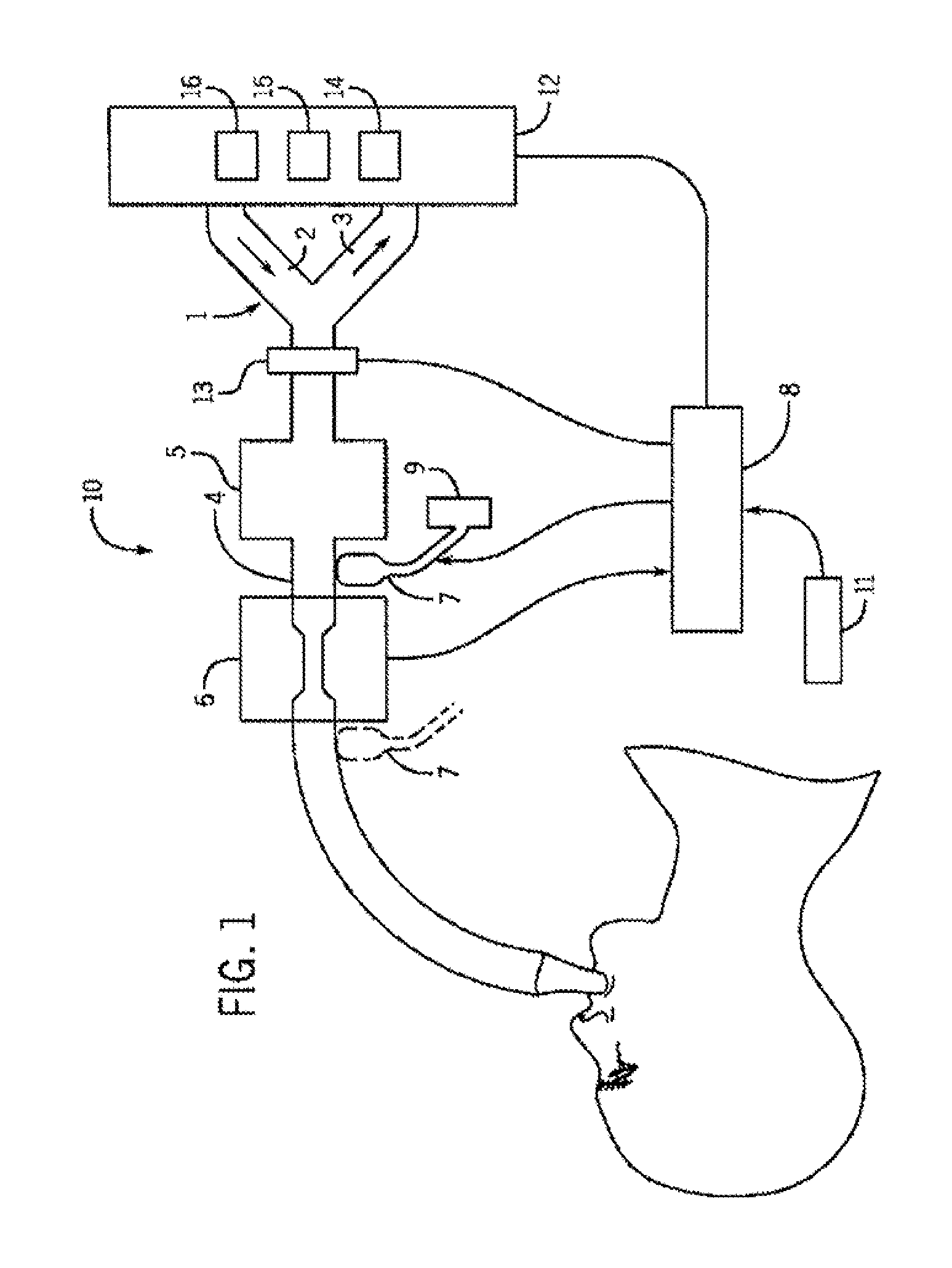
[0025]FIG. 1 shows an anesthesia delivery system 10 comprising a breathing connector 1, such as Y-piece, having three branches. The first branch is an inhalation tube 2 for delivery of inhaled gases during an inspiration, the second branch is an exhalation tube 3 carrying expired gas during an expiration and the third branch is an airway tube 4 carrying during the inspiration the inhaled gas to and during the expiration the expired gas from a subject. Also the anesthesia delivery system 10 may comprise an anesthetic agent adsorber unit 5, such as a reflector, for adsorbing an anesthetic agent usually when a subject is exhaling and for releasing this agent into inspiratory breathing air. Further the anesthesia delivery system 10 comprises a gas analyzing apparatus 6 and an anesthetic agent dosing unit 7, which both are assembled into the airway tube 4. The gas analyzing apparatus 6, such as an infrared gas analyzer, is for measuring a concentration of at least one component of a gas ...


PUM


Abstract

An apparatus for administering an anesthetic agent for a subject breathing. The apparatus includes a liquid reservoir for an anesthetic agent and an anesthetic agent dosing unit in fluid connection with the liquid reservoir and which anesthetic agent dosing unit is connectable to an airway tube for delivering breathing gases to a subject, said dosing unit including a first member to produce anesthetic agent droplets having a diameter less than 100 μm.

Description

CROSS-REFERENCE TO RELATED APPLICATIONS[0001]This application claims priority under 35 U.S.C. § 119(a)-(d) or (f) to prior-filed, co-pending European patent application serial number 08396007.0, filed on May 20, 2008, which is hereby incorporated by reference in its entirety.STATEMENT REGARDING FEDERALLY SPONSORED RESEARCH OR DEVELOPMENT[0002]Not ApplicableNAMES OF PARTIES TO A JOINT RESEARCH AGREEMENT[0003]Not ApplicableREFERENCE TO A SEQUENCE LISTING, A TABLE, OR COMPUTER PROGRAM LISTING APPENDIX SUBMITTED ON COMPACT DISC[0004]Not ApplicableBACKGROUND OF THE INVENTION[0005]1. Field of the Invention[0006]The field of the invention relates to an apparatus, a system and a method for administering an anesthetic agent for a subject breathing.[0007]2. Description of Related Art[0008]While anestetizing patients anesthetic agent is typically held in a vessel having a liquid space and a gas space in which vessel the agent is vaporized into a carrying gas, which may require heating dependin...

Claims


Application Information

Patent Timeline
IPC IPC(8): A61M16/18A61M19/00
CPCA61M16/18A61M2016/103A61M2230/432
Inventor HAVERI, HEIKKIHEINONEN, ERKKI
Owner GENERAL ELECTRIC CO
Why Eureka
Try Eureka