Method and apparatus for varying an impedance

a technology of impedance and variable impedance, applied in the field of variable impedance, can solve the problems of critical loss, loss of transmitted power, and inability to solve basic needs, and achieve the effect of improving the response rate of the circuit and easy increasing the rate of recursion

Active Publication Date: 2009-11-26
RFMICRON
View PDF9 Cites 30 Cited by
  • Summary
  • Abstract
  • Description
  • Claims
  • Application Information

AI Technical Summary

Benefits of technology

[0035]In accordance with another preferred embodiment of my invention, I provide a tuning circuit for dynamically varying the impedance of a tank circuit comprising an inductor and a capacitor, the capacitance of which can be selectively varied. In my preferred tuning circuit, a reference voltage generator, coupled to the tank circuit, produces a reference voltage proportional to the response of the tank circuit to a received signal. A differentiator, coupled to the generator, then determines the polarity of the change in the reference voltage between a first point in time and a second point in time. Next, a direction selector, coupled to the differentiator and adapted to respond to the determined polarity, selects one of two different directions in which the capacitance of the capacitor can be varied. Finally, a ramp generator, coupled to the selector and to the capacitor, selectively varies the capacitance of the capacitor in the currently-selected direction. As with my preferred method, my preferred tuning circuit is inherently recursive in operation, and the initially selected rate of recursion can be easily increased, decreased or even stopped under appropriate conditions.

Problems solved by technology

Furthermore, it is of no relevance in such systems which specific voltage levels are selected to represent each of the logic states.
It is well known that mismatch between fC and fR results in loss of transmitted power.
In some applications, this may not be of particular concern, but, in others, such as in RF identification (“RFID”) applications, such losses are of critical concern.
Although it would be highly desirable to have a single design that is useful in all systems, one very significant issue in this regard is the lack of international standards as to appropriate RFID system frequencies, and, to the extent there is any de facto standardization, the available frequency spectrum is quite broad: Low-Frequency (“LF”), including 125-134.2 kHz and 140-148.f kHz; High-Frequency (“HF”) at 13.56 MHz; and Ultra-High-Frequency (“UHF”) at 868-928 MHz.
However, such structural improvements, while valuable, do not solve the basic need for a variable impedance circuit having a relatively broad tuning range.

Method used


Image

  • Method and apparatus for varying an impedance
  • Method and apparatus for varying an impedance
  • Method and apparatus for varying an impedance

Examples


Embodiment Construction

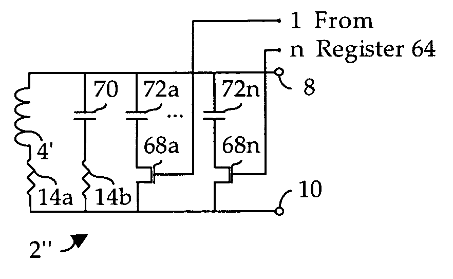
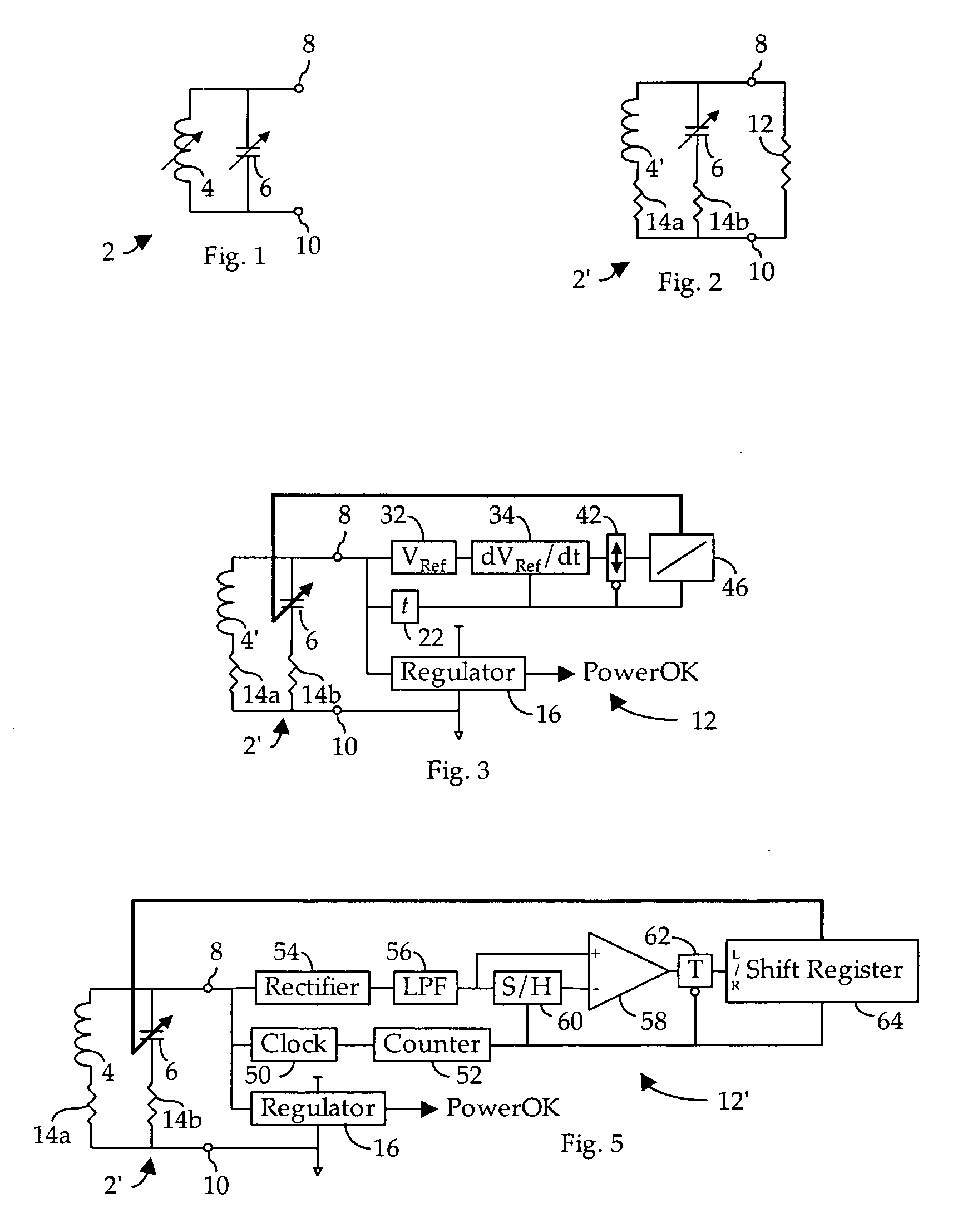
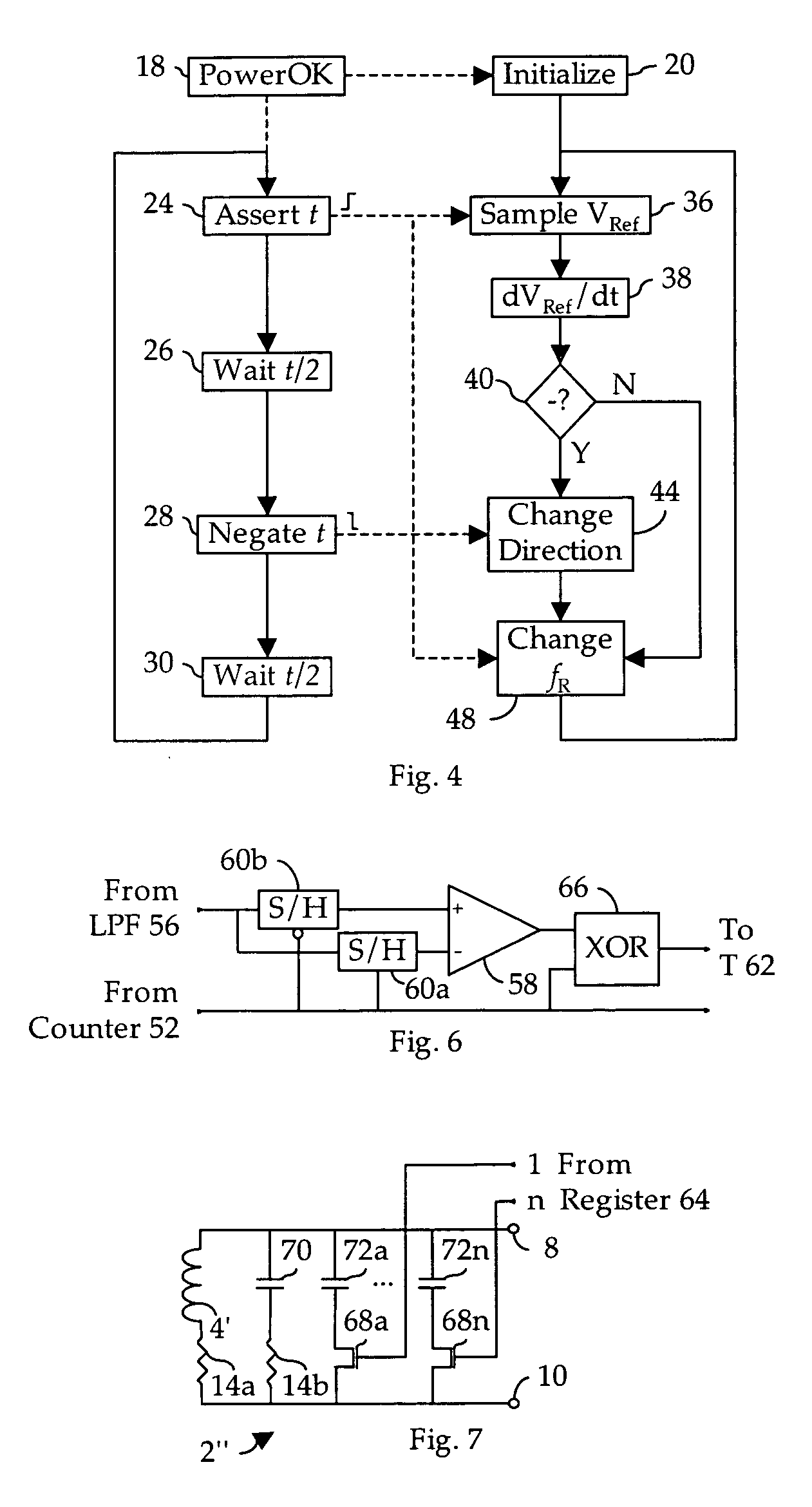
[0046]As shown in the variable tank circuit 2′ in FIG. 2, in many applications, such as RFID tags, it may be economically desirable to substitute for variable inductor 4 a fixed inductor 4′. In addition, one must take into consideration the inherent input resistance, Ri, of the load circuit 12, as well as the parasitic resistances 14a of inductor 4′ and 14b of capacitor 6.

[0047]In accordance with the preferred embodiment of my invention as shown in FIG. 3, the amplitude modulated (“AM”) signal broadcast by the reader in an RFID system will be magnetically coupled to a conventional coil antenna comprising inductor 4′, and a portion of the induced current is extracted via nodes 8 and 10 by a regulator 16 to produce operating power for all other circuits. Once sufficient stable power is available, regulator 16 will produce a PowerOK signal to initiate system operation (see, 18 and 20 in FIG. 4). If desired, a variable resistor (not shown) can be provided in parallel with inductor 4′, g...


PUM


Abstract

A method and apparatus for dynamically varying the impedance of a tank circuit whereby, over time, the response of the circuit to a received signal is maximized.

Description

BACKGROUND OF THE INVENTION[0001]1. Field of the Invention[0002]The present invention relates generally to variable impedances, and, in particular, to a variable impedance for use in a tank circuit.[0003]2. Description of the Related Art[0004]In general, in the descriptions that follow, I will italicize the first occurrence of each special term of art which should be familiar to those skilled in the art of radiofrequency (“RF”) communication systems. In addition, when I first introduce a term that I believe to be new or that I will use in a context that I believe to be new, I will bold the term and provide the definition that I intend to apply to that term. In addition, throughout this description, I will sometimes use the terms assert and negate when referring to the rendering of a signal, signal flag, status bit, or similar apparatus into its logically true or logically false state, respectively, and the term toggle to indicate the logical inversion of a signal from one logical st...

Claims


Application Information

Patent Timeline
Patent Type & Authority Applications(United States)
IPC IPC(8): H03H7/00
CPCH03H7/40H03J2200/10H03J3/20
Inventor ROKHSAZ, SHAHRIAR
Owner RFMICRON
Why Eureka
Try Eureka