Moving-Coil Planar Speaker

a planar speaker and moving coil technology, applied in the field of loudspeakers, can solve the problems of speaker thereby suffering a less satisfactory low-frequency performance, speaker's dynamic range being seriously affected, and the driver not being able to exert enough driving for

Inactive Publication Date: 2009-11-26
KAM TAI YAN
View PDF1 Cites 10 Cited by
  • Summary
  • Abstract
  • Description
  • Claims
  • Application Information

AI Technical Summary

Benefits of technology

[0012]The surround is made of a flexible material and is positioned between the circumference of the front opening of the frame and the edge of the diaphragm. The surround, on one hand, suppresses the vibration of the diaphragm at its edge and, on the other hand, prevents the sound waves at either side of the diaphragm from interfering with each other.
[0014]The suspension elements are made of a flexible element and contain a wave-like segment. The suspension elements therefore could vibrate with the diaphragm and, on the other hand, the first symmetric bending mode of the diaphragm along its longer side is also constrained by the suspension elements. The areas near the two ends of the diaphragm, which vibrates at a phase opposite to the central area of the diaphragm, would be reduced. The speaker therefore would enjoy a relatively flat frequency response in the middle-frequency range and a superior sound quality.

Problems solved by technology

The speaker's frequency response is shifted towards the mid- and high-frequency ranges and the speaker thereby suffers a less satisfactory low-frequency performance.
On the other hand, if the driver's outer diameter and the size of the magnet are reduced to maintain the original bandwidth, the driver wouldn't be able to exert enough driving force and the speaker's dynamic range would be seriously affected.
In other words, conventional speaker design approaches are not appropriate for the elongated planar speaker.
Such a sudden sound pressure drop in the middle-frequency range would seriously affect the reproduced sound quality of the speaker.

Method used


Image

  • Moving-Coil Planar Speaker
  • Moving-Coil Planar Speaker
  • Moving-Coil Planar Speaker

Examples


first embodiment

[0031]As shown in FIGS. 5, 6, and 7, a planar speaker according to the present invention mainly contains a frame 11, a diaphragm 12, a driver 13, two suspension elements 14, and a surround 15. The frame 11 has a flat rectangular shape and the surround 15 is positioned between the circumference of a front opening of the frame 11 and the edge of the diaphragm 12. The diaphragm 12 is thereby suspended in the front opening of the frame 11 by the surround 15. The surround 15, on one hand, suppresses the vibration of the diaphragm 12 at its edge and, on the other hand, prevents the sound waves at either side of the diaphragm 12 from interfering with each other. The driver 13 is positioned in the center of the frame 11 behind the diaphragm 12. A voice coil of driver 13 is attached to a back surface of the diaphragm 12 so that a back-and-forth movement of the coil would cause the diaphragm 12 to vibrate and to produce sound waves.

[0032]Two beams 112 are arranged in parallel along a back ope...

third embodiment

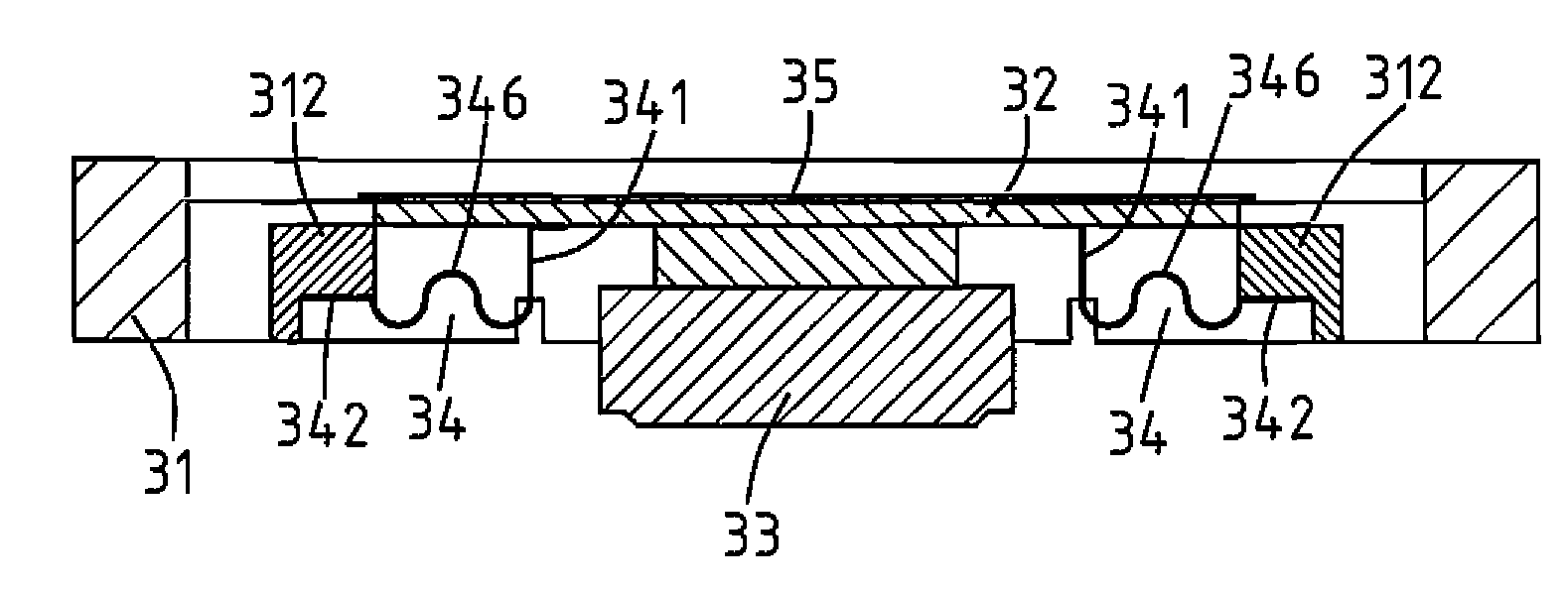
[0035]the present invention is shown in FIGS. 11 and 12. As illustrated, the planar speaker, similar to the previous embodiment, also contains a frame 31, a diaphragm 32, a driver 33, two suspension elements 34, and a surround 35. The frame 31 has a flat rectangular shape and the diaphragm 32 is suspended in a front opening of the frame 31 by the surround 35. The driver 33 is positioned in the center of the frame 31 behind the diaphragm 32. A voice coil of driver 33 is attached to a back surface of the diaphragm 32 so that a back-and-forth movement of the coil would cause the diaphragm 32 to vibrate and to produce sound waves.

[0036]Two beams 312 are arranged in parallel on either side of the driver 33 between two opposing longer side walls of the frame 31 and behind the diaphragm 32. The suspension elements 34 are made of a flexible material such as foam, rubber, plastic, or a composite material. Each suspension element 34 contains a vertical first arm segment 341, a lateral second ...


PUM


Abstract

The planar speaker contains a frame, a diaphragm, a driver, a surround, and a number of flexible suspension elements. The diaphragm is suspended in a front opening of the frame by the surround. The driver is positioned at the center of the frame and a voice coil of the driver is attached to a back surface of the diaphragm. Two beams are arranged in parallel between two opposing longer wall segments of the frame on either side of the driver. The suspension elements are supported by the two beams, respectively, and attached to a back surface of the diaphragm. The symmetric deformation of the diaphragm along its longer side is thereby constrained by the suspension elements and the deformations at the two end zones of the diaphragm vibrating at a phase opposite to that of the center of the diaphragm would be suppressed.

Description

BACKGROUND OF THE INVENTION[0001]1. Field of the Invention[0002]The present invention generally relates to loudspeakers, and more particularly to a moving-coil planar speaker.[0003]2. Description of Related Art[0004]As shown in FIGS. 1 and 2, a conventional moving-coil planar speaker usually contains a frame 1, a conepaper or diaphragm 2, a driver 3, and a surround 4. The frame 1 is basically has flat rectangular shape with a front opening. The frame 1 is mainly formed by a rectangular side wall 102 perpendicularly surrounding the circumference of a back wall 108. The side wall 102 is composed of a pair of opposing short wall segments 104 and a pair of opposing long wall segments 106. Assuming that the short wall segments 104 have a length a and the long wall segments 106 have a length b, then a is less or equal to b. The driver 3 is fixedly positioned at the center of the back wall 108 and is enclosed by the side wall 102. The surround 4 is a ring of flexible material (such as foam...

Claims


Application Information

Patent Timeline
Patent Type & Authority Applications(United States)
IPC IPC(8): H04R1/00
CPCH04R9/043H04R31/006H04R9/046
Inventor KAM, TAI YAN
Owner KAM TAI YAN
Why Eureka
Try Eureka