
Residential Recycling Bin

Inactive Publication Date: 2009-12-03
ORBIS CANADA
View PDF10 Cites 16 Cited by
  • Summary
  • Abstract
  • Description
  • Claims
  • Application Information

AI Technical Summary

Benefits of technology

[0017]According to the first aspect, the bin further comprises a handle, wherein the handle is configured to be freely rotatable, and further wherein the handle can be rotated to a resting position upon a top portion of the rear wall; a rear base groove, located at a rearward portion of the base; and a rear wall lower lip, located at a lowermost portion of the rear wall, wherein the rear base groove and the rear wall lower lip of a first upper bin are configured to jointly operate to fit about the handle of a substantially similar second lower bin, when the handle of the second lower bin is in the resting position, to substantially prevent the first upper bin from sliding or moving forward with respect to the second lower bin.
[0023]According to a third aspect of the present invention, a bin is provided comprising: a base, a left sidewall, a right sidewall, a front wall; a rear wall, all fixedly connected to each other, wherein the left sidewall extends from the base at a first predetermined angle to the base, the right sidewall extends from the base at a second predetermined angle to the base, the front wall extends from the base at a third predetermined angle to the base, and the rear wall extends from the base at a fourth predetermined angle to the base; a handle, wherein the handle is configured to be freely rotatable, and further wherein the handle can be rotated to a resting position upon a top portion of the rear wall; a rear base groove, located at a rearward portion of the base; and a rear wall lower lip, located at a lowermost portion of the rear wall, wherein the rear base groove and the rear wall lower lip of a first upper bin are configured to jointly operate to fit about the handle of a substantially similar second lower bin, when the handle of the second lower bin is in the resting position, to substantially prevent the first upper bin from sliding or moving forward with respect to the second lower bin.
[0027]According to a fourth aspect of the present invention, a method for using a residential recycling bin is provided, comprising the steps of: inserting a liner into the residential recycling bin; inserting a first upper portion of the liner into a first inverted “V”-shaped liner retainer, and a second upper portion of the liner into a second inverted “V”-shaped liner retainer, wherein the first and second inverted “V”-shaped liner retainers are configured to substantially prevent the liner from slipping into an interior portion of the residential recycling bin; and placing recyclable materials into the liner.
[0028]According to a fifth aspect of the present invention, a method is provided for using a residential recycling bin, wherein the bin includes a rotatable handle, the method comprising the steps of: inserting a liner into the residential recycling bin; positioning a portion of the liner over an upper portion of a rear wall of the residential recycling bin; placing the handle in a liner storage position, such that the handle forms a substantially even, planar surface with upper portions of left and right sidewalls of the residential recycling bin, whereby the liner is substantially prevented from slipping into an interior portion of the residential recycling bin; and placing recyclable materials into the liner.

Problems solved by technology

Thus, all of the cited prior art references have deficiencies that make known recycling bins substantially more difficult to use.

Method used


Image

  • Residential Recycling Bin
  • Residential Recycling Bin
  • Residential Recycling Bin

Examples


Embodiment Construction

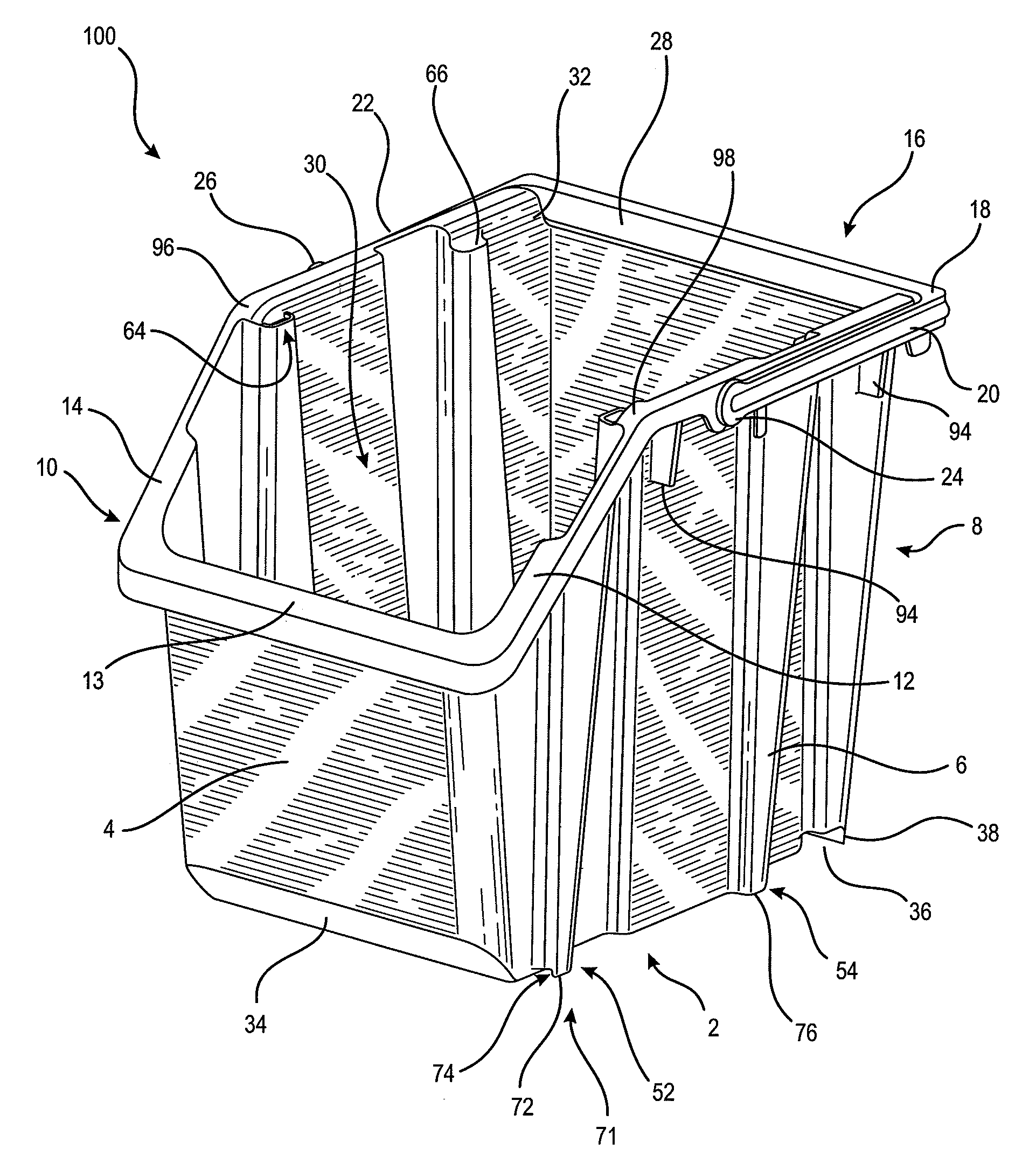
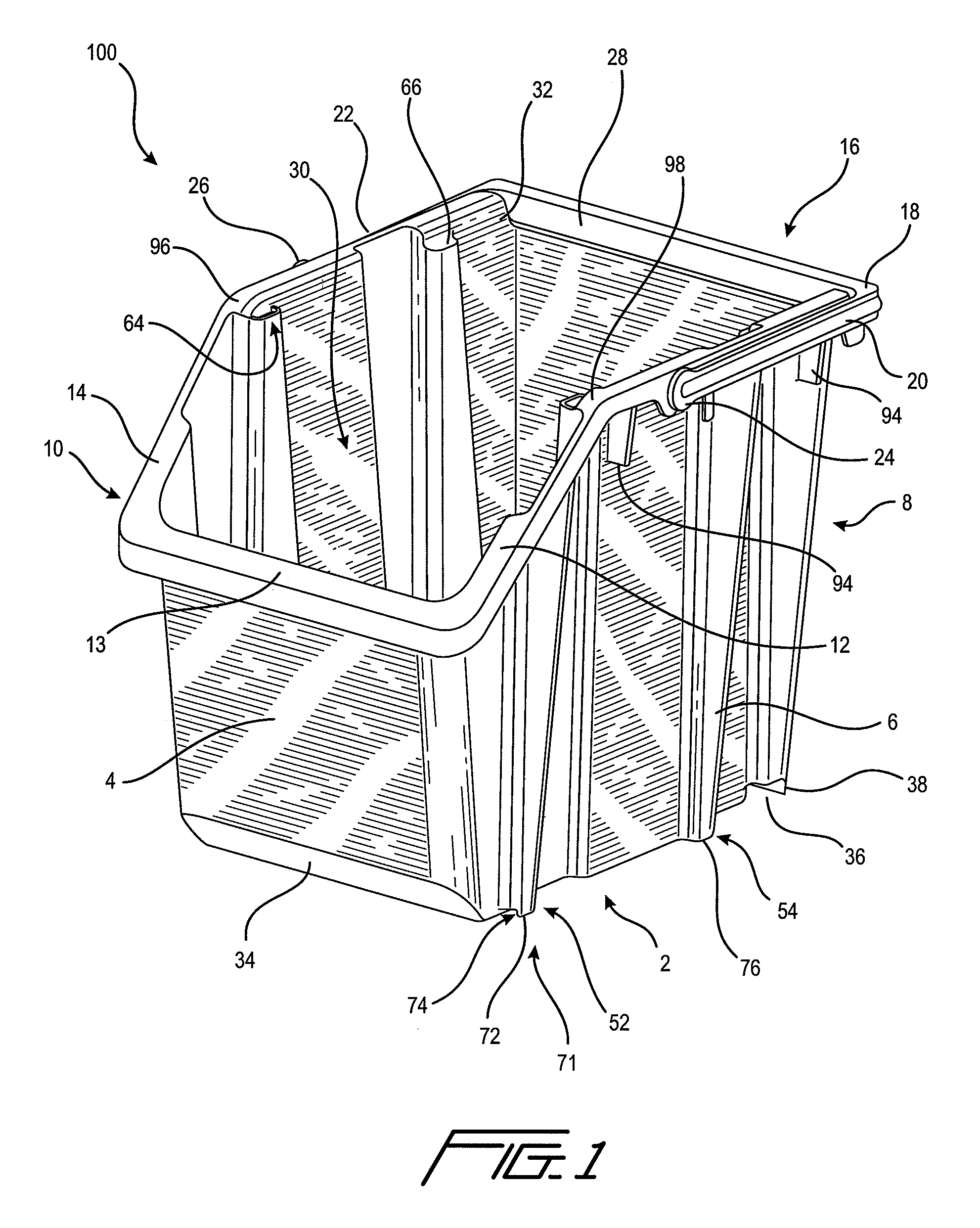
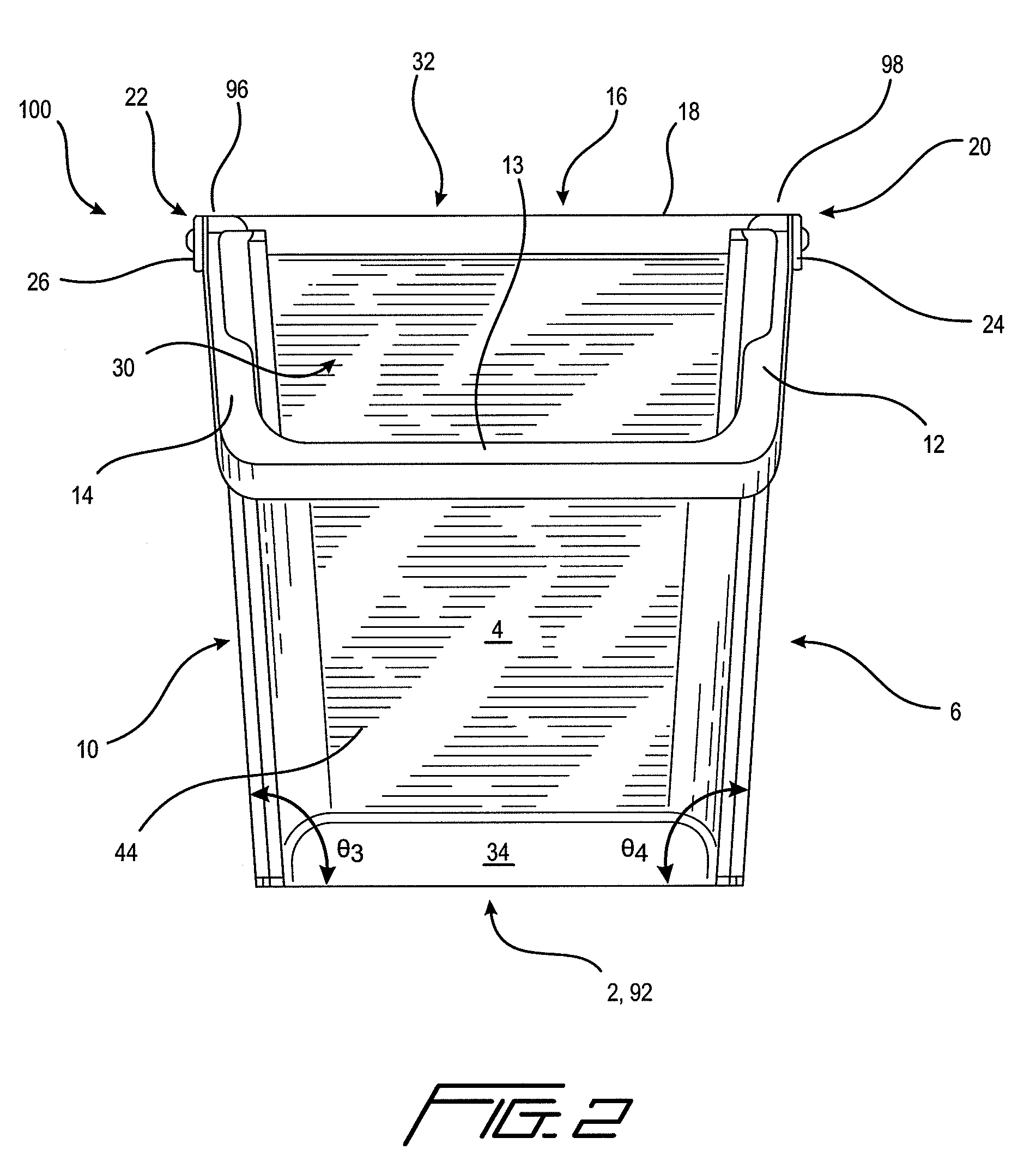
[0062]The various features of the preferred embodiments will now be described with reference to the drawing figures, in which like parts are identified with the same reference characters. The following description of the presently contemplated best mode of practicing the invention is not to be taken in a limiting sense, but is provided merely for the purpose of describing the general principles of the invention.

[0063]I. Introduction

[0064]Residential recycling bin (bin) 100 according to exemplary embodiments comprises front wall 4, left side wall 6, rear wall 8, right side wall 10, and base 2. Front wall 4 and rear wall 8 are connected to base 2, as are left and right side walls 6, 10. According to a preferred embodiment, left and right sidewalls 6, 10 are formed at a predetermined angle of about 93.5° with respect to base 2, and as such, facilitate nesting of one or more bins 100 into one another, for purposes of storage. According to a preferred embodiment, front wall 4 and rear wa...


PUM


Abstract

A bin and method for its use in recycling residential recyclable materials are described. The bin comprises a left and right sidewall, a base, and front wall; the front wall is lower than the other three walls, and when two bins are stacked in a 0° stacking configuration, the lower front wall of the lower bin and a sloped surface on the lower portion of the upper bin create a recyclable receiving chute that accepts recyclable materials freely. When in the stacked configuration, the upper bin is substantially securely held to the lower bin by a combination of a channel on the lower rear portion of the base that fits over a handle that rests upon on upper portion of the rear wall. Furthermore, a lower lip on the lower portion of the rear wall aligns with the handle and substantially prevents front-wards and backwards motion of the upper bin. The handle can facilitate retention of the liner as well, by holding the liner against the upper portion of the rear wall. The rear wall comprises a top open portion within which a portion of the handle can fit, thereby forming a substantially planar surface among the upper portions of the left and right sidewalls, and the handle. A plurality of inverted “V” shaped liner retainers secure liners to help prevent their being dragged into the interior portion of the bin.

Description

BACKGROUND OF THE INVENTION[0001]1. Field of the Invention[0002]The invention relates to plastic bins. More particularly, the invention relates to a home or residential recycling system and method for its use.[0003]2. Background Art[0004]With the increased concern and awareness for the environment throughout the world, recycling has become an accepted part of modern society. Many different common everyday items that can be recycled include: glass; metals; plastics; paper; and various other products. For example, in various localities within the United States, people are accustomed to recycling plastic, metals and glass certain days of the week with their garbage collection, and on other days, paper materials can be collected for recycling. These recycled products are then commonly bundled and sold to manufacturers or fabricators of various components that utilize these materials or sold in bulk for reuse in producing new items.[0005]Accordingly, recycling bins are common in the prio...

Claims


Application Information

Patent Timeline
IPC IPC(8): B65D35/14
CPCB65D21/0216B65D21/048B65D25/2855B65F2220/124B65F1/06B65F1/1468B65F2220/12B65F1/02
Inventor MARTHEENAL, BASIL T.
Owner ORBIS CANADA
Features
  • Generate Ideas
  • Intellectual Property
  • Life Sciences
  • Materials
  • Tech Scout
  • Unparalleled Data Quality
  • Higher Quality Content
  • 60% Fewer Hallucinations
Learn More