Snap-in cable hanger clip
a technology of cable hanger and clip, which is applied in the direction of machine supports, support parts, and support accessories of scaffolds, etc., can solve the problems of crowded tunnels and towers of antennas
- Summary
- Abstract
- Description
- Claims
- Application Information
AI Technical Summary
Benefits of technology
Problems solved by technology
Method used
Image
Examples
Embodiment Construction
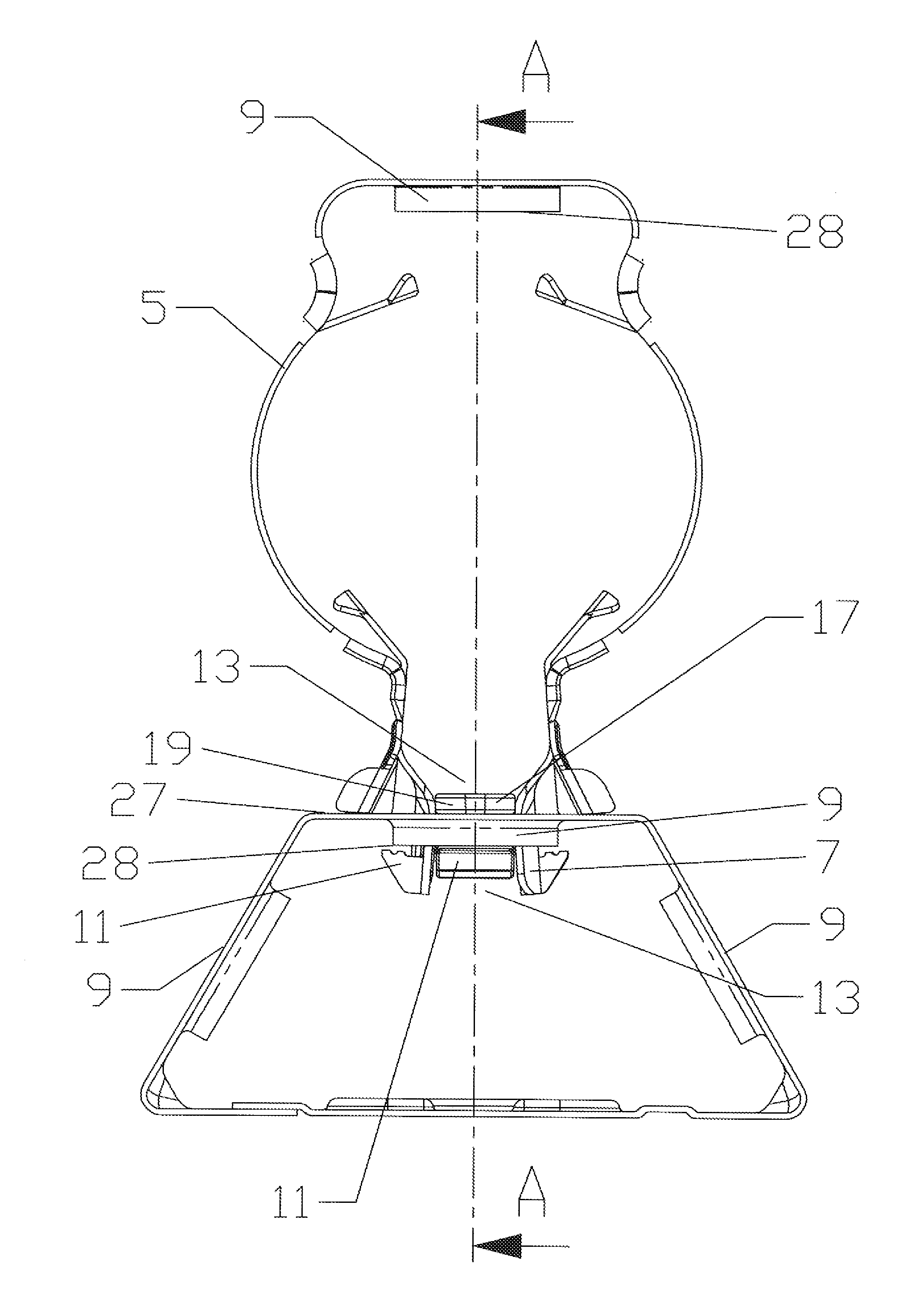
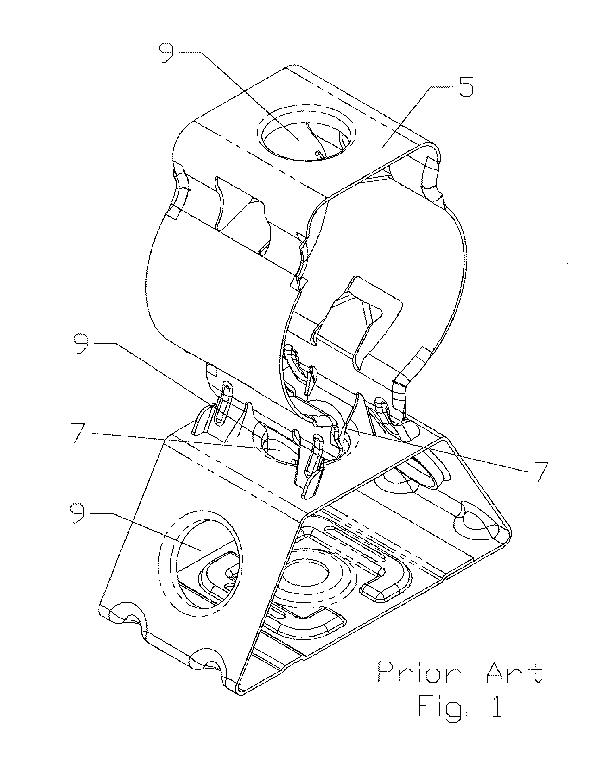
[0024]The inventor has analyzed the maximum load and failure characteristics of a snap-in cable hanger 5, for example as shown in FIG. 1. The inventor discovered that a frequent point of failure under excessive load is a twisting and or shift of the leg(s) 7 of the hanger body with respect to the mounting hole which allows retaining features of the legs, such as locking barb(s) 11, to disengage completely and or shift far enough from the seated position to where they can be deformed until they then disengage.
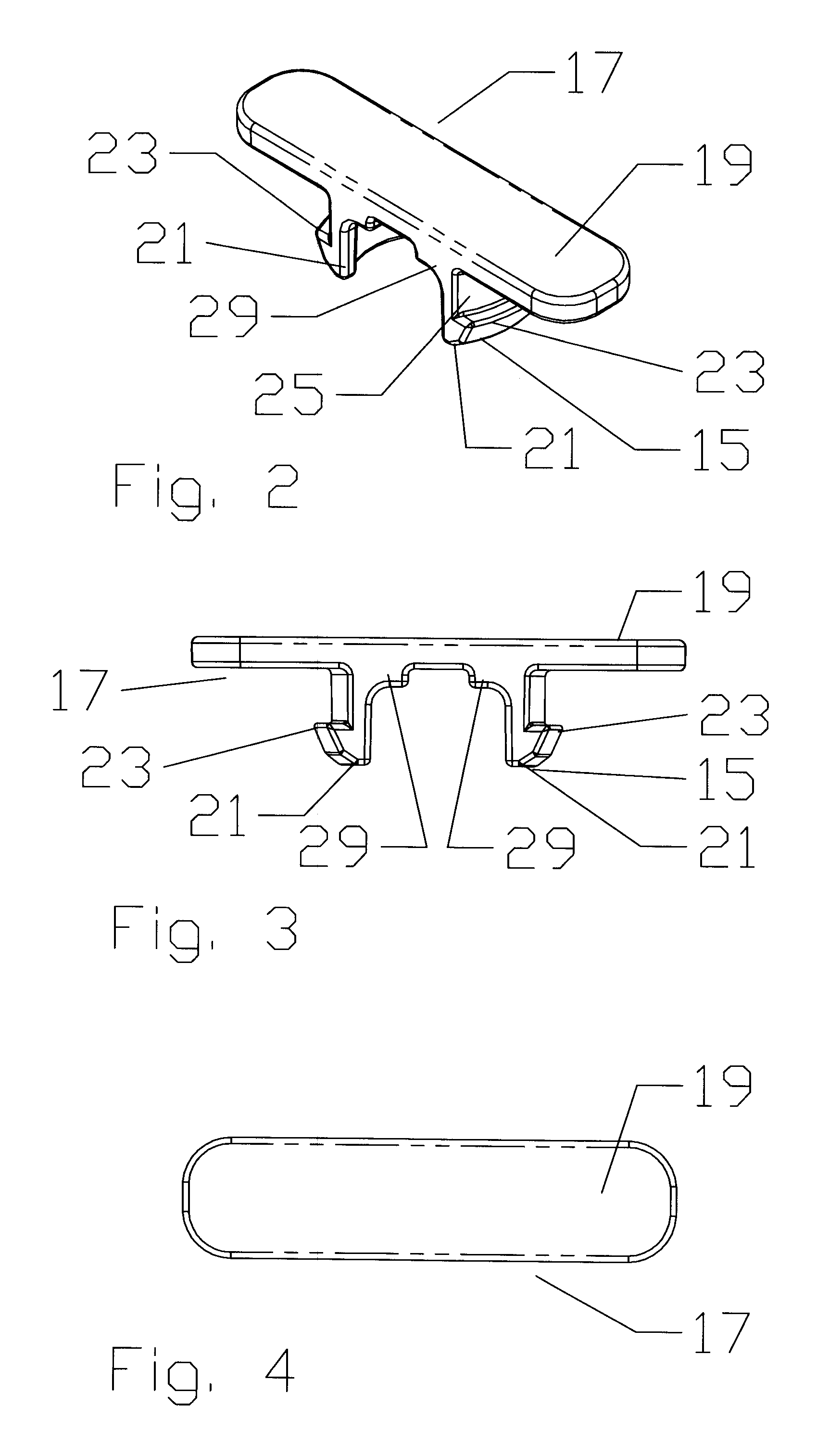
[0025]During mounting, the leg(s) 7 of a typical snap-in cable hanger 5 are deflected towards one another into a spring space 13 between the leg(s) 7 to enable clearance of locking barb(s) 11, projecting from a distal end 15 of each leg 7, through the mounting hole 9. Once passed through the mounting hole 9, the leg(s) 7 are allowed to spring back into a mounted configuration where each is biased outwards against the mounting hole 9 sidewall, the locking barb(s) 11 overhanging a...
PUM
| Property | Measurement | Unit |
|---|---|---|
| diameter | aaaaa | aaaaa |
| length | aaaaa | aaaaa |
| width | aaaaa | aaaaa |
Abstract
Description
Claims
Application Information
 - R&D
- Intellectual Property
- Life Sciences
- Materials
- Tech Scout
- Unparalleled Data Quality
- Higher Quality Content
- 60% Fewer Hallucinations
Browse by: Latest US Patents, China's latest patents, Technical Efficacy Thesaurus, Application Domain, Technology Topic, Popular Technical Reports.
© 2025 PatSnap. All rights reserved.Legal|Privacy policy|Modern Slavery Act Transparency Statement|Sitemap|About US| Contact US: help@patsnap.com


