Textile gas guide for inflatable curtain

a technology of inflatable curtains and gas guides, which is applied in the direction of pedestrian/occupant safety arrangements, vehicular safety arrangements, vehicle components, etc., can solve the problems of increasing the cost of airbag systems, increasing the tooling and equipment costs associated with the overall cost of inflatable curtains, and rigid gas guides increasing the weight of airbag units, etc., to achieve the effect of reducing cost and increasing the pressure that inventive textile gas guides can withstand

Active Publication Date: 2009-12-03
AUTOLIV ASP INC
View PDF9 Cites 18 Cited by
  • Summary
  • Abstract
  • Description
  • Claims
  • Application Information

AI Technical Summary

Benefits of technology

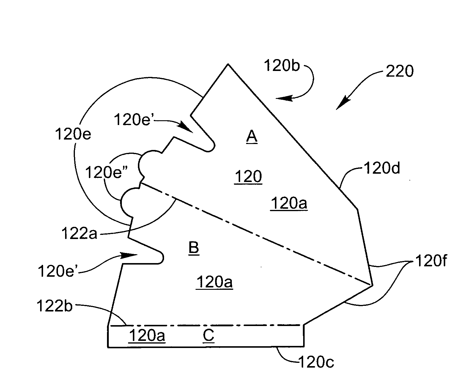
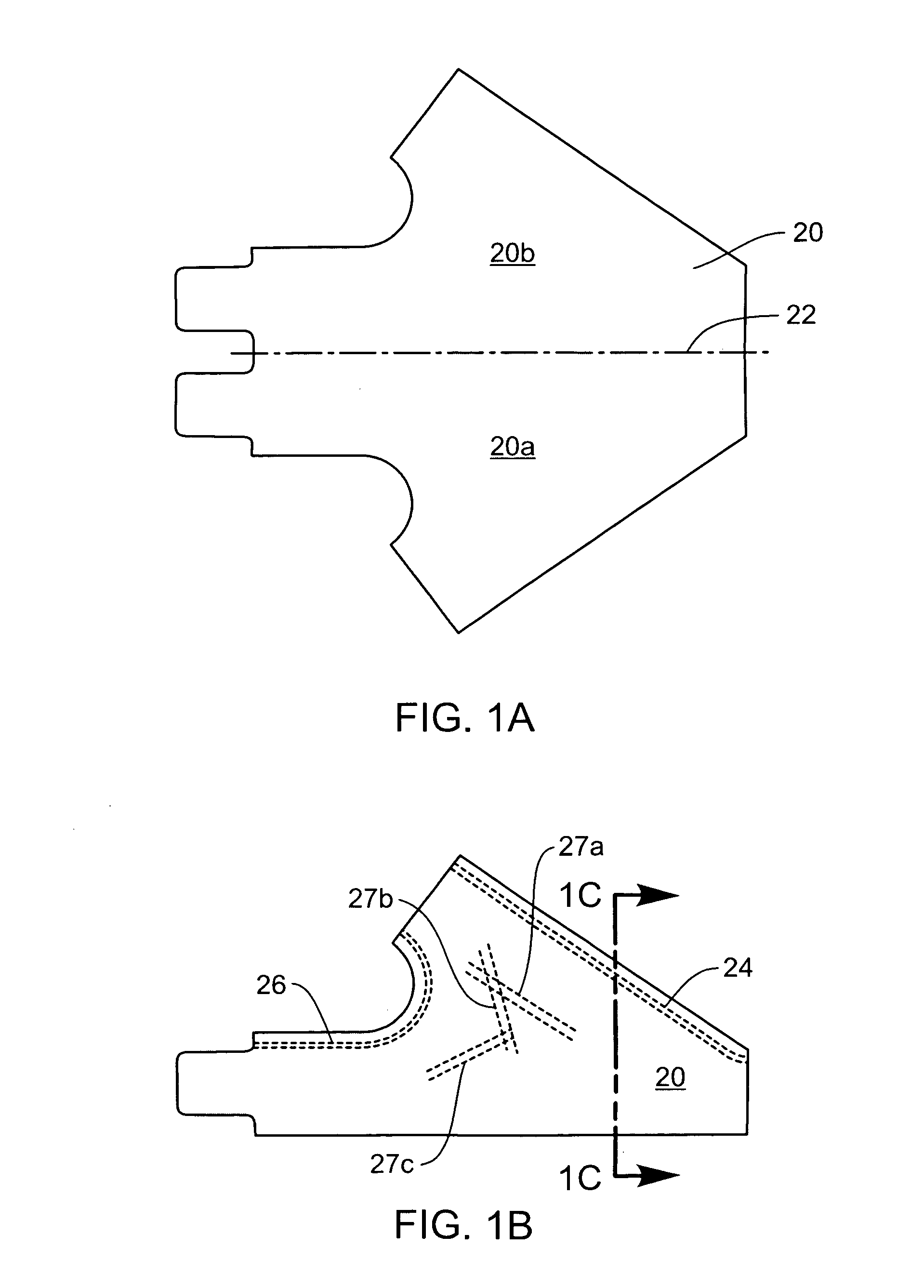
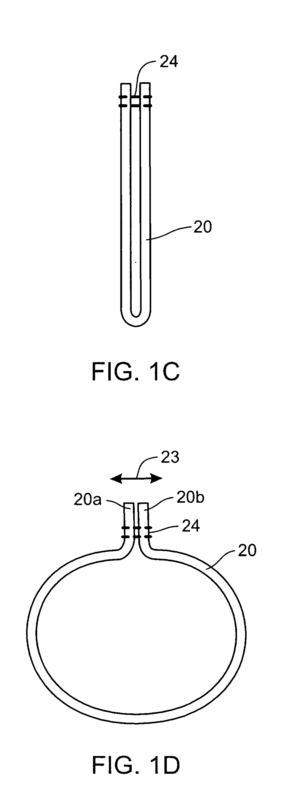
[0012]The use of the overlapping region may provide significant embodiments. As described above, the overlapping region is formed by overlapping the obverse side with a portion of the reverse side. When this gas guide with the overlapping region is filled with gas, the pressure of the gas within the gas guide presses outwards against the overlapping portion. The pressure stress resulting from the obverse side attempting to pull away from the reverse side at the first seam due to the pressure exerted by the inflation gas. (This stress is referred to as sheer stress herein). The gas guides utilize a seam that is placed under shear stress, rather than tensile stress, when inflated. This increases the pressure that the inventive textile gas guide can withstand and removes the need for a rigid gas guide. Therefore, airbag modules may be manufactured at a lower cost.

Problems solved by technology

The gas guide is manufactured separate from the airbag cushion and, thus, increases tooling and equipment costs associated with the overall cost of the inflatable curtain.
The rigid gas guide also increases the weight of the airbag unit.
The inclusion of this rigid gas guide increases the costs of the airbag system.

Method used


Image

  • Textile gas guide for inflatable curtain
  • Textile gas guide for inflatable curtain
  • Textile gas guide for inflatable curtain

Examples


Embodiment Construction

[0045]The presently preferred embodiments of the present invention will be best understood by reference to the drawings, wherein like parts are designated by like numerals throughout. It will be readily understood that the components of the present invention, as generally described and illustrated in the figures herein, could be arranged and designed in a wide variety of different configurations. It should also be understood that the figures are not necessarily to scale. Thus, the following more detailed description of the embodiments of the present invention, as represented in the FIGS. 3A-8, is not intended to limit the scope of the invention, as claimed, but is merely representative of presently preferred embodiments of the invention.

[0046]Furthermore, the particular features, structures, or characteristics may be combined in any suitable manner in one or more embodiments. In the following description, numerous specific details are provided to convey a thorough understanding of e...


PUM

PropertyMeasurementUnit
lengthaaaaaaaaaa
widthaaaaaaaaaa
lengthaaaaaaaaaa

Abstract

A textile gas guide may include a fabric member which may include an obverse side, a reverse side, a leading edge, and a trailing edge. The fabric member may overlap upon itself at least once such that at least a portion of the obverse side adjacent the leading edge may be disposed to align with at least a portion of the reverse side adjacent the trailing edge to define an overlapping region. A first seam may be sewn through the overlapping region, the first seam being in shear stress when the airbag module is inflated. An airbag module may include the above textile gas guide and an airbag cushion including an inflation throat. At least a portion of the textile gas guide may be located within the inflation throat. An inflator may be inserted into the textile gas guide.

Description

TECHNICAL FIELD[0001]The present invention relates to textile gas guides for inflatable curtains. More specifically, the present invention relates to methods of manufacturing textile gas guides that reduces the likelihood that the seam of the textile gas guides will fail during deployment.BACKGROUND OF THE INVENTION[0002]The inclusion of inflatable safety restraint devices, or airbags, is now a legal requirement for many new vehicles. Airbags are typically installed in the steering wheel dashboard, and at other positions in the vehicle. In the event of an accident, an accelerometer within the vehicle measures the abnormal deceleration and triggers the expulsion of rapidly expanding gases from an inflator. The expanding gases fill the airbags, which immediately inflate in front of the driver and passenger to protect them from impact against the windshield, dashboard, or other surfaces of the vehicle interior. Side impact airbags, known as inflatable curtains, have also been developed...

Claims


Application Information

Patent Timeline
Patent Type & Authority Applications(United States)
IPC IPC(8): B60R21/26B32B7/08B60R21/16
CPCB60R21/232B60R2021/23533B60R21/235B60R21/2346
Inventor WOLD, DANANELSON, JAMES E.CZACH, BRIANHATFIELD, MARK S.
Owner AUTOLIV ASP INC
Why Eureka
Try Eureka