Turf Playing Surface Aeration and Drainage System

a drainage system and turf technology, applied in the field of subsurface aeration and drainage systems, can solve the problems of reducing efficiency and effectiveness, reducing the effective cross section of pipes, and reducing air flow through pipes and ultimately from the tur

Inactive Publication Date: 2009-12-03
HUMMERT GEORGE T +1
View PDF6 Cites 10 Cited by
  • Summary
  • Abstract
  • Description
  • Claims
  • Application Information

AI Technical Summary

Benefits of technology

[0019]Further, the invention includes sloping the drain pipe downward from the air/water separator to position the flow control unit at a lower elevation than the separator to promote water drainage to the drain outlet and establi

Problems solved by technology

First, since the blowers are normally designed to move air, not heavy water particles, both efficiency and effectiveness are reduced when significant quantities of water become mixed in the air stream.
Secondly, water tends to collect at low elevation regions or “saddles” in the pipes which reduces the effective cross section of pipe, thereby reducing air flow through the pipes and

Method used


Image

  • Turf Playing Surface Aeration and Drainage System
  • Turf Playing Surface Aeration and Drainage System
  • Turf Playing Surface Aeration and Drainage System

Examples


Embodiment Construction

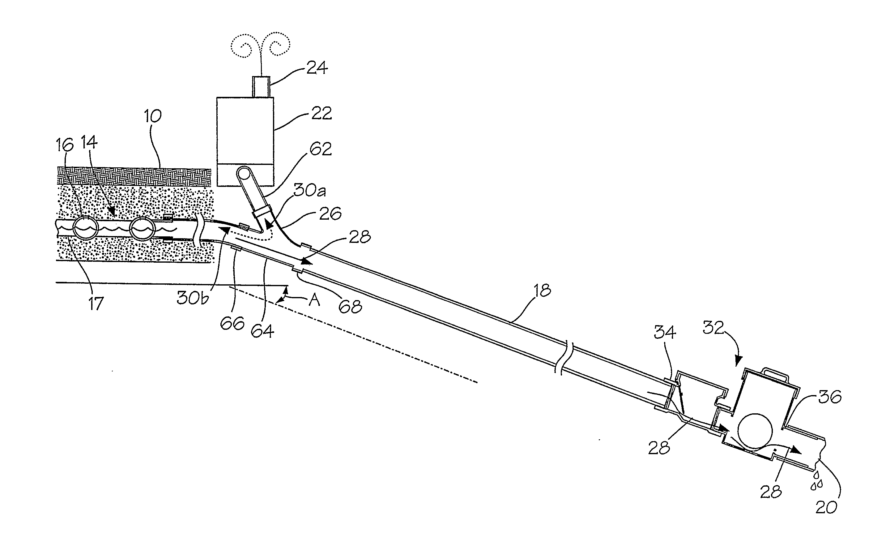
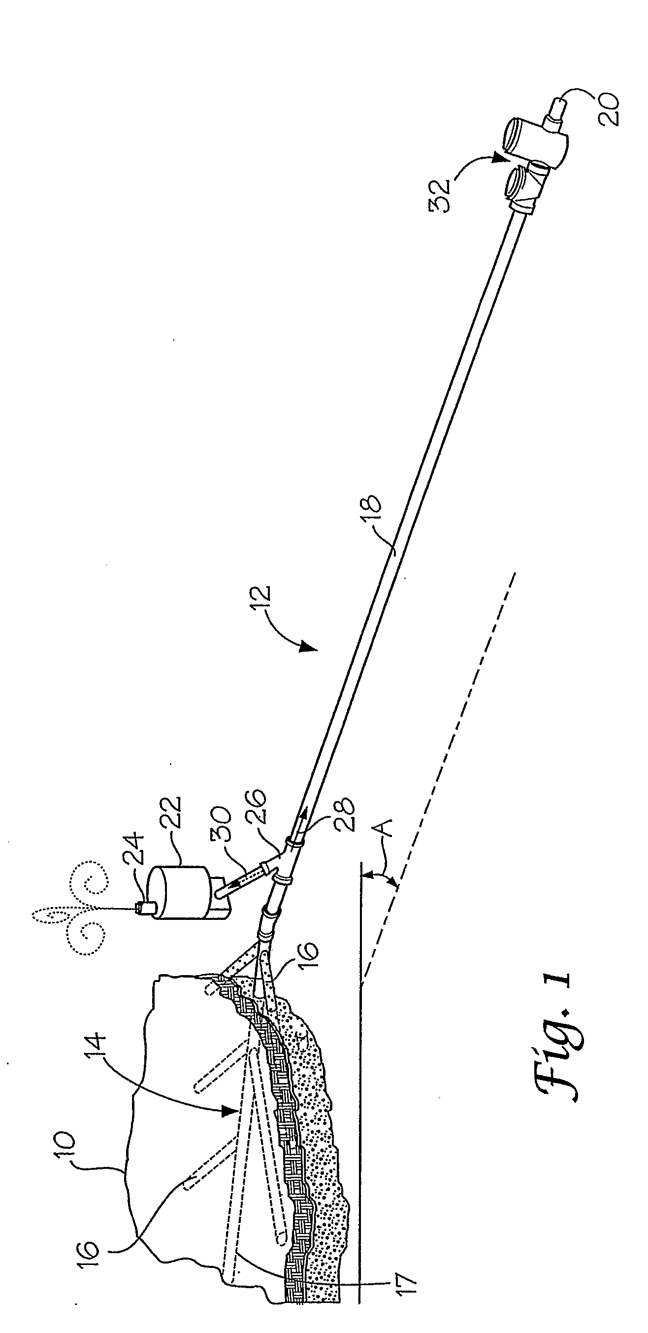
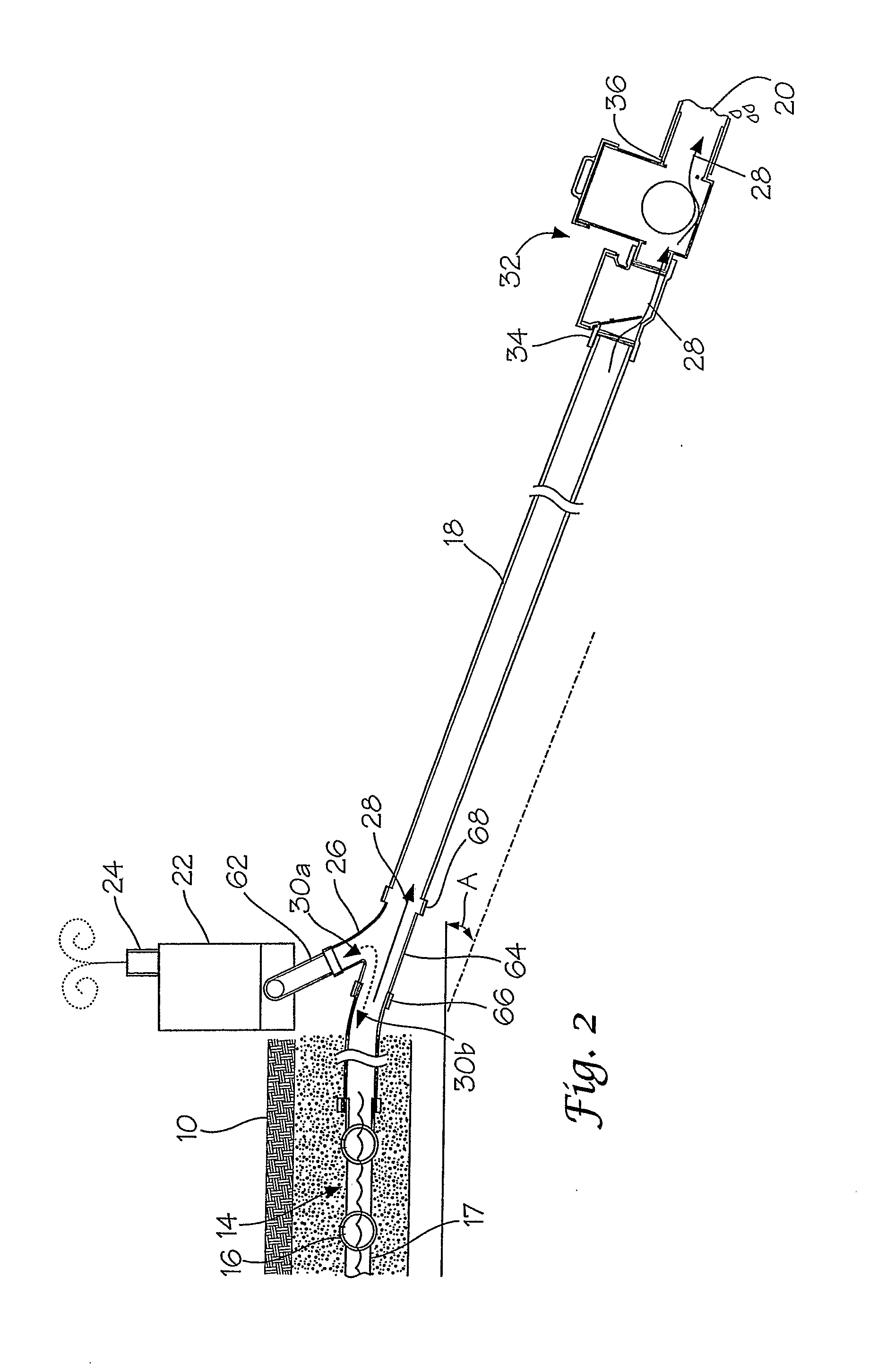
[0026]With reference to the drawings, the invention will now be described in more detail. Referring to FIG. 1, a turf playing surface, designated generally as 10, is shown having an aeration and drainage system, designated generally as 12, for controlling water drainage from the playing surface, as well as aerating the playing surface to promote turf growth and maintenance.

[0027]Aeration and drainage system 12 includes a fluid flow network, designated generally as 14, having a plurality of perforated pipes 16 and a manifold pipe 17 installed beneath playing surface 10 through which an air flow passes for aerating and removing water from the playing surface. Fluid flow network 14 further includes a drain pipe 18 for channeling the water to a drain outlet 20, which typically may empty the water into a collection pond.

[0028]A blower 22 is operatively connected in fluid communication with fluid flow network 14 for creating an air flow 30 through the flow network, and in particular, thro...


PUM


Abstract

A perforated pipe network beneath a playing surface. A blower connected to the pipe network drawing an air flow through the pipe network to create a vacuum. A drain pipe connecting to the pipe network. An air/water separator connected upstream of the blower for separating water from the air flow prior to entering the blower and channeling the water into the drain pipe for discharge. A flow control unit having a unit inlet connected to the drain pipe downstream of the air/water separator and a unit outlet discharging water to a drain outlet. The flow control unit blocking air flow through the unit inlet into the drain pipe when the blower is in the vacuum mode, and opening the unit inlet when a waterhead buildup at the unit inlet exceeds the vacuum level established by the blower to discharge water through the drain outlet.

Description

CROSS REFERENCE TO RELATED APPLICATION[0001]This application claims priority from a provisional application filed Mar. 17, 2005 under Ser. No. 60 / 662,913, and a non-provisional application filed Mar. 31, 2005 under Ser. No. 11 / 094,995.BACKGROUND OF THE INVENTION[0002]1) Field of the Invention[0003]The present invention relates generally to subsurface aeration and drainage systems, and more particularly, to a combination pressure and vacuum valve assembly for maintaining atmospheric isolation of the subsurface system while separating water from air and draining the water out of the system.[0004]2) Description of Related Art[0005]Subsurface systems have been developed for removing water and aerating turf on sports fields and golf greens. A typical system is comprised of a network of interconnected drainage pipe located beneath a region of turf and a blower connected in such a manner that a partial vacuum or differential pressure can be created in the drainage network. Water drains fro...

Claims


Application Information

Patent Timeline
IPC IPC(8): E02B11/00
CPCE01C13/083F16K24/06F16K21/20
Inventor HUMMERT, GEORGE T.HARTENSTEIN, FREDRICK O.
Owner HUMMERT GEORGE T
Why Eureka
Try Eureka