Multibeam refect array

a multi-beam refect array and antenna technology, applied in the field of repeaters, can solve the problems of high losses, increased user concentration, and increased difficulty in installing repeaters, especially in urban areas

Inactive Publication Date: 2009-12-03
TELEFON AB LM ERICSSON (PUBL)
View PDF4 Cites 29 Cited by
  • Summary
  • Abstract
  • Description
  • Claims
  • Application Information

AI Technical Summary

Problems solved by technology

In telecommunications systems such as, for example, cellular telephony systems in the microwave range, there can be a number of problems for a base station when trying to communicate with the users located in the area covered by the base station.
In urban areas, examples of such problems can be high rise building which obstruct the line of sight to certain sub-areas, or that in certain sub-areas the concentration of users can exceed that which can be handled by the base station.
Installing such repeaters, especially in urban areas, is becoming increasingly difficult, due to a number of factors such as aesthetic considerations and difficulties in finding sufficient space for a repeater site.
Such a repeater would suffer from a number of drawbacks, for example high losses due to low directivity, and would generally not be suitable for use in urban areas.

Method used


Image

  • Multibeam refect array
  • Multibeam refect array
  • Multibeam refect array

Examples


Embodiment Construction

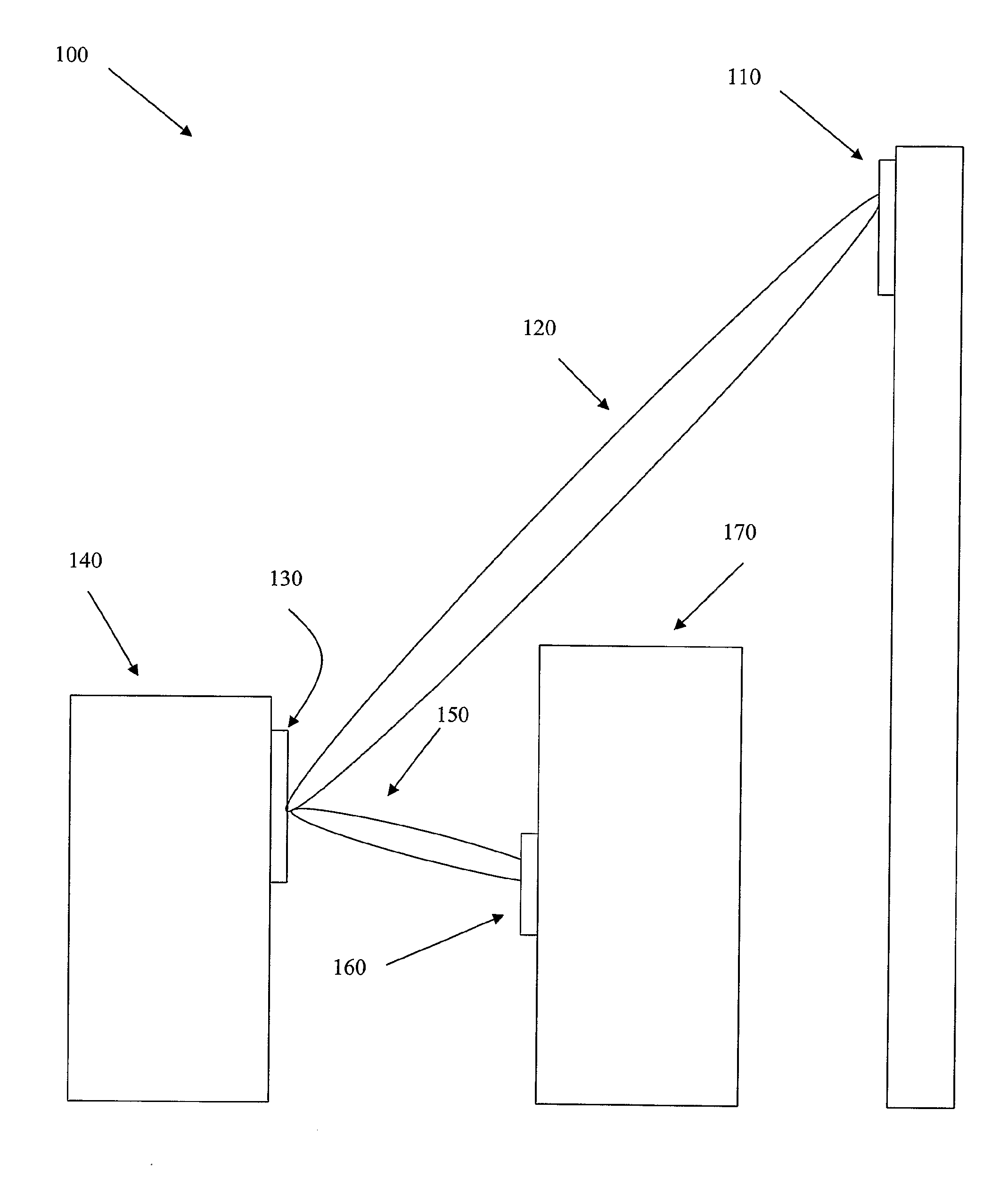
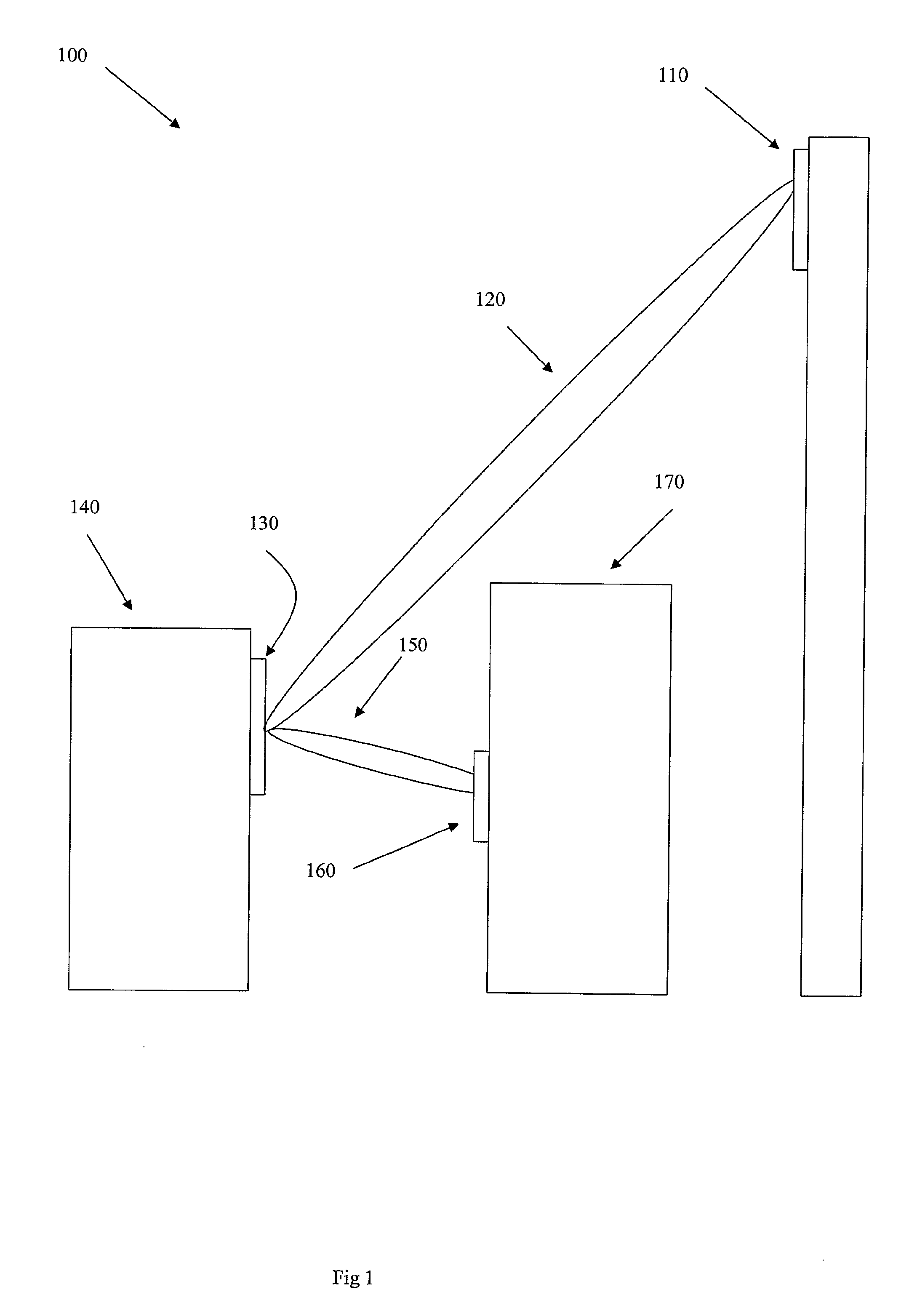
[0013]FIG. 1 shows a system 100 in which a repeater antenna of the invention may be used. The system 100 shown is a cellular telephony system, which should be seen merely as an example of an embodiment intended to facilitate the explanation of the invention, the repeater antenna can be used in a wide variety of other applications, as will be realized by those skilled in the field.

[0014]A first radio unit 110, in this case a radio base station in the cellular system 100, is unable to provide adequate service to an area in its cell, since a building 170 obscures the area from radio coverage by the base station 110.

[0015]In order to service the obscured area, a second radio unit or base station 160 has been deployed on the building 170, so that the antenna of the station 160 can cover the obscured area. The second radio unit 160 may be a base station similar to the base station 110, but it can also be a base station with a reduced capacity compared to the base station 110, a so called ...


PUM


Abstract

The invention discloses a repeater antenna for use in point-to-point applications in telecommunications systems in the microwave range, intended for connecting transmissions from a first radio unit at a first site to a second radio unit at a second site. The repeater antenna is essentially plane, and is designed as a traveling wave antenna with at least a first and a second antenna beam, so that the first beam can be used for transmissions to and from said first radio unit, and the second beam can be used for transmissions to and from said second radio unit.

Description

TECHNICAL FIELD[0001]The invention discloses a repeater antenna for use in point-to-point applications in telecommunications systems in the microwave range, the repeater antenna being intended for connecting transmissions from a first radio unit at a first site to a second radio unit at a second site.BACKGROUND ART[0002]In telecommunications systems such as, for example, cellular telephony systems in the microwave range, there can be a number of problems for a base station when trying to communicate with the users located in the area covered by the base station. In urban areas, examples of such problems can be high rise building which obstruct the line of sight to certain sub-areas, or that in certain sub-areas the concentration of users can exceed that which can be handled by the base station.[0003]One way of handling these problems is to install other base stations which can cover the sub-areas in question, usually base stations with smaller capacity, so called “pico-stations”. Th...

Claims


Application Information

Patent Timeline
Patent Type & Authority Applications(United States)
IPC IPC(8): H04B7/15
CPCH01Q13/206H01Q21/065H01Q25/004H01Q21/08H04B7/1555H01Q11/02H01Q13/20H01Q21/06H04B7/155
Inventor ANDERSSON, MATS H.HALLBJORNER, PAULRYDBERG, ANDERS
Owner TELEFON AB LM ERICSSON (PUBL)
Why Eureka
Try Eureka