Power control system, power monitoring device, record medium having power monitoring program recorded therein, and power monitoring method

a power control system and monitoring device technology, applied in the direction of electric controllers, ignition automatic control, instruments, etc., can solve the problems of complex configuration of each device, inability to comprehensively manage the power supply source, and the device stops, so as to reduce the processing load of each device and simplify the configuration

Active Publication Date: 2009-12-03
RAKUTEN GRP INC
View PDF13 Cites 23 Cited by
  • Summary
  • Abstract
  • Description
  • Claims
  • Application Information

AI Technical Summary

Benefits of technology

[0008]The present invention has been accomplished in consideration of the foregoing problems, and an object thereof lies in a point of realizing the power source redundancy of each device constructing the network while suppressing the processing load of each device with a simplified configuration.

Problems solved by technology

Well, establishing the power source redundancy in the device itself, as described above, causes a problem that the device stops in the case that a failure has occurred in the power supply source.
Further, it causes a problem that the power supply source cannot be comprehensively managed as the entirety of the system connected via the network because the power source is managed as a single device.
This could cause a configuration of each device to become complicated and further, the cost to be augmented.
In addition hereto, the above technology causes a problem that a processing load of each device could be increased because each device needs to perform a power control process with a power control function, namely, a receipt / supply amount of the power or the like needs to be computed device by device.

Method used


Image

  • Power control system, power monitoring device, record medium having power monitoring program recorded therein, and power monitoring method
  • Power control system, power monitoring device, record medium having power monitoring program recorded therein, and power monitoring method
  • Power control system, power monitoring device, record medium having power monitoring program recorded therein, and power monitoring method

Examples


example

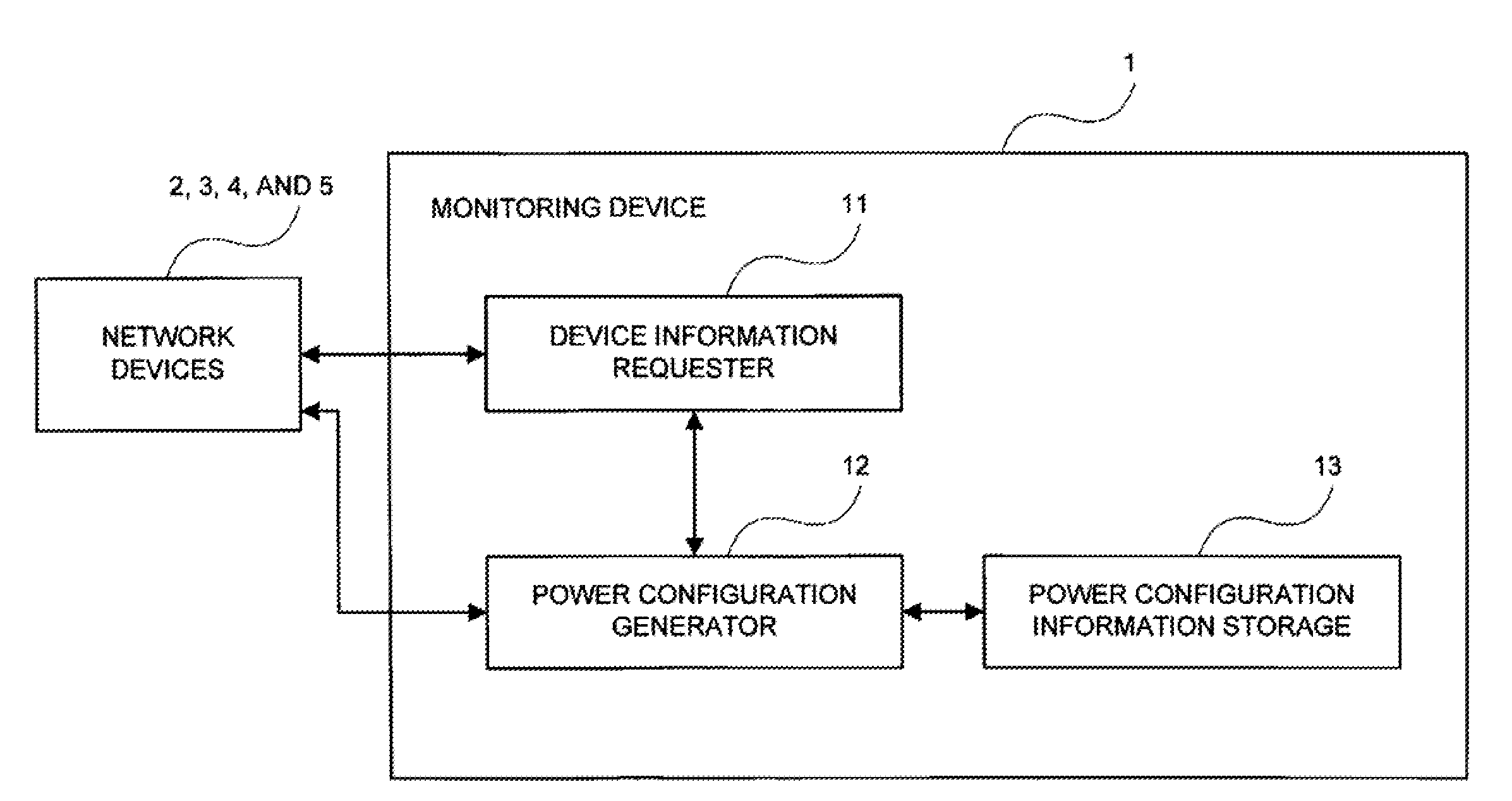
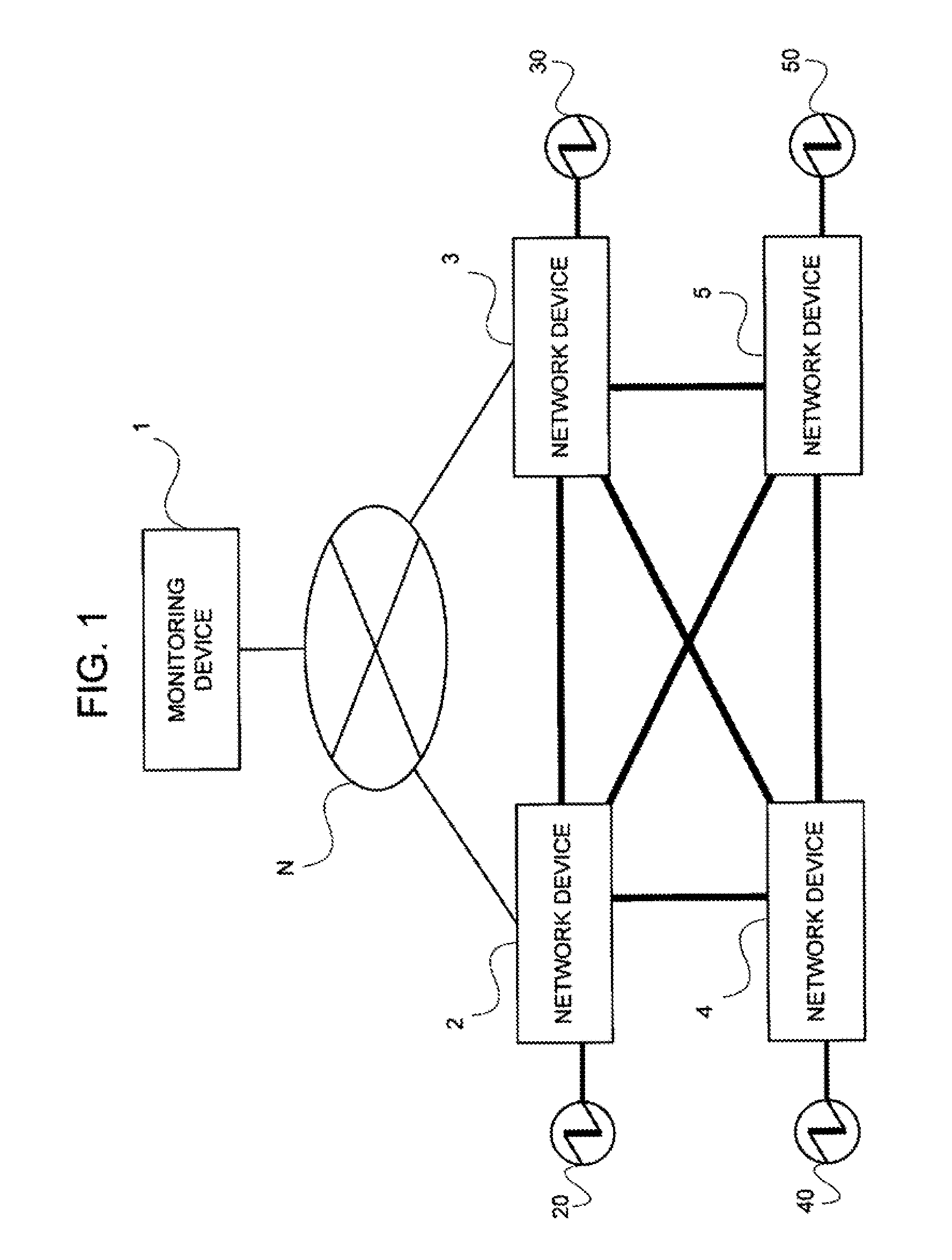
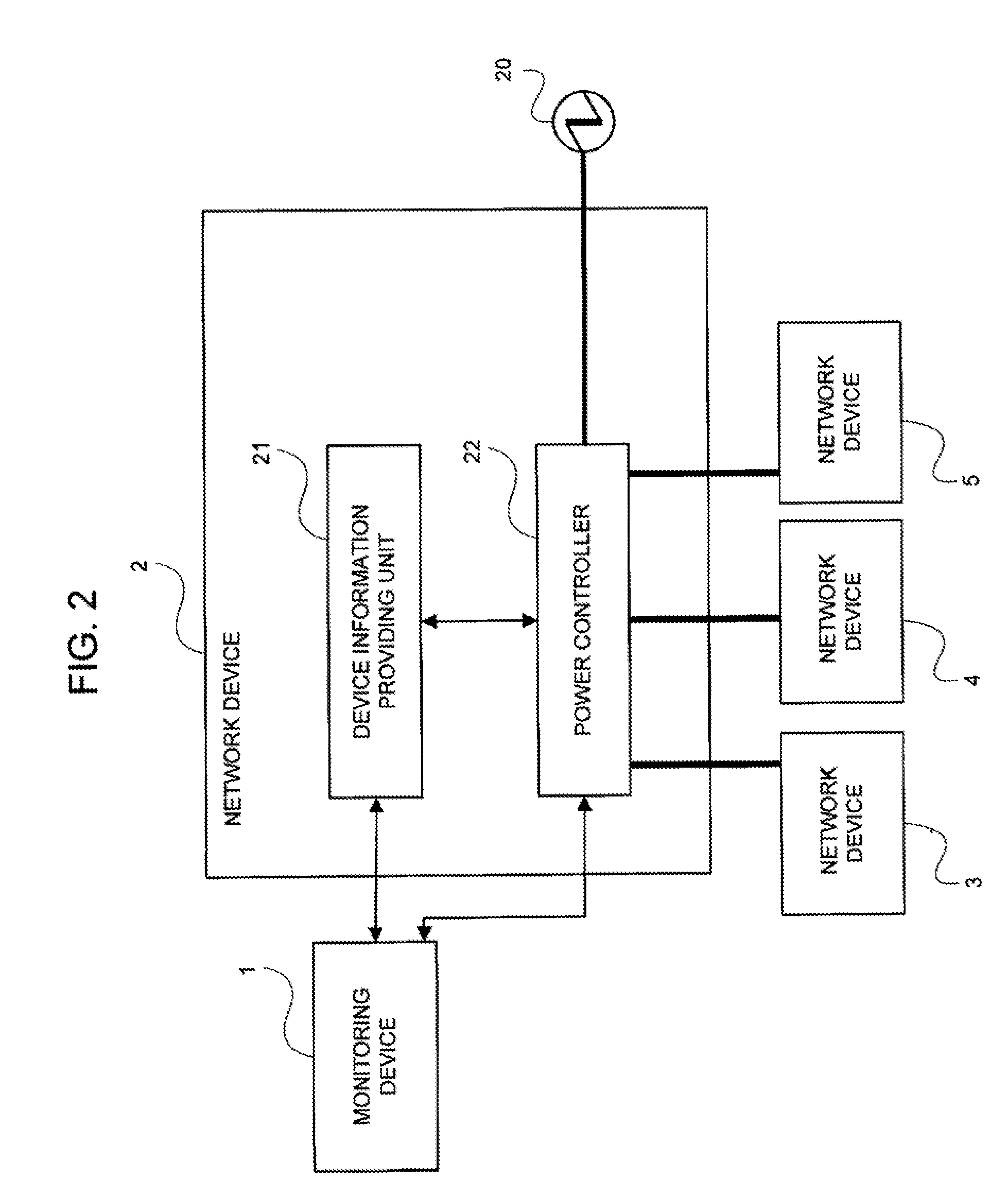
[0048]The example of the present invention will be explained by making a reference to FIG. 1 to FIG. 10. FIG. 1 is a block diagram illustrating an entire configuration of the power monitoring system. FIG. 2 is a functional block diagram illustrating of a configuration of the network device. FIG. 3 is a functional block diagram illustrating a configuration of the monitoring device. FIG. 4 is a sequence block illustrating an operation of the power monitoring system. Each of FIG. 5 and FIG. 6 is a flowchart illustrating an operation of the monitoring device. Each of FIG. 7 to FIG. 10 is a view for explaining a situation of a power control in the power monitoring system.

[0049][Configuration]

[0050]The power control system in this example, as shown in FIG. 1, includes plural network devices 2, 3, 4, and 5 (monitored devices) connected to each other via a network N, and a monitoring device 1 (power monitoring device) for monitoring powers of these devices. Additionally, in this example, th...


PUM


Abstract

The present invention has an object of realizing a power source redundancy of each of devices constructing a network while suppressing a processing load of each device with a simplified configuration. A power monitoring device includes a power configuration generator for preparing power control information based upon device information including necessary power information, being information indicative of a power necessary for operating each monitored device itself, and power status information indicative of a received power in each monitored device, causing a power configuration information storage to store the prepared power control information, and further transmitting the prepared power control information to each monitored device. Further, the monitored device includes a power controller for controlling the power of its own device based upon the transmitted power control information.

Description

INCORPORATION BY REFERENCE[0001]This application is based upon and claims the benefit of priority from Japanese patent application No. 2008-144039, filed on Jun. 2, 2008, the disclosure of which is incorporated herein in its entirety by reference.RELATED ART[0002]The present invention relates to a power control system, and more particular to a power control system for controlling at least one of a power supply and a power receipt in devices connected to each other via a network, and demanding a power.[0003]Nowadays, various kinds of electric appliances such as an information processing device and a household electronic have prevailed and are being used, and a high reliability is required for the electric appliances. In particular, a countermeasure at the time of a power source failure is of importance and a power source redundancy needs to be realized because it is essential to supply the power source to the electric appliance. As a configuration for realizing the foregoing power so...

Claims


Application Information

Patent Timeline
Patent Type & Authority Applications(United States)
IPC IPC(8): G06F1/28G06F1/26
CPCH04L12/10G06F1/3209
Inventor SUZUKI, YOUJI
Owner RAKUTEN GRP INC
Why Eureka
Try Eureka