
Model-based process simulation systems and methods

Active Publication Date: 2009-12-03
ASML NETHERLANDS BV
View PDF21 Cites 54 Cited by
  • Summary
  • Abstract
  • Description
  • Claims
  • Application Information

AI Technical Summary

Benefits of technology

The patent describes a method for simulating the performance of a chip design using virtual measurements. These results can identify areas of the design that may not be optimal and suggest ways to improve them. The method also takes into account the limitations of the actual scanner used to produce the virtual measurements, which can influence the redesign of the chip. Overall, this approach can help designers create better performing chips.

Problems solved by technology

The technical problem addressed in this patent text is the inconsistent and unpredictable results that can occur when using different types of lithographic projection apparatus, or scanners, to create patterns on a substrate. This is due to the different optical proximity effects exhibited by each scanner, which can cause variations in the CD (critical dimension) of the pattern. The current trial and error process used to adjust the scanners and processes is expensive and time-consuming. The patent proposes a solution to this problem by introducing a common process for imaging patterns with different types of scanners, which can help to ensure consistent and acceptable patterns.

Method used


Image

  • Model-based process simulation systems and methods
  • Model-based process simulation systems and methods
  • Model-based process simulation systems and methods

Examples


Embodiment Construction

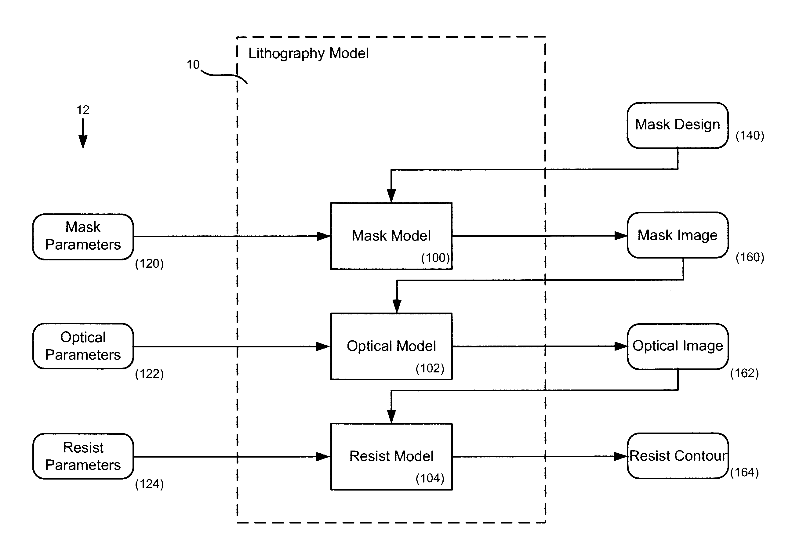
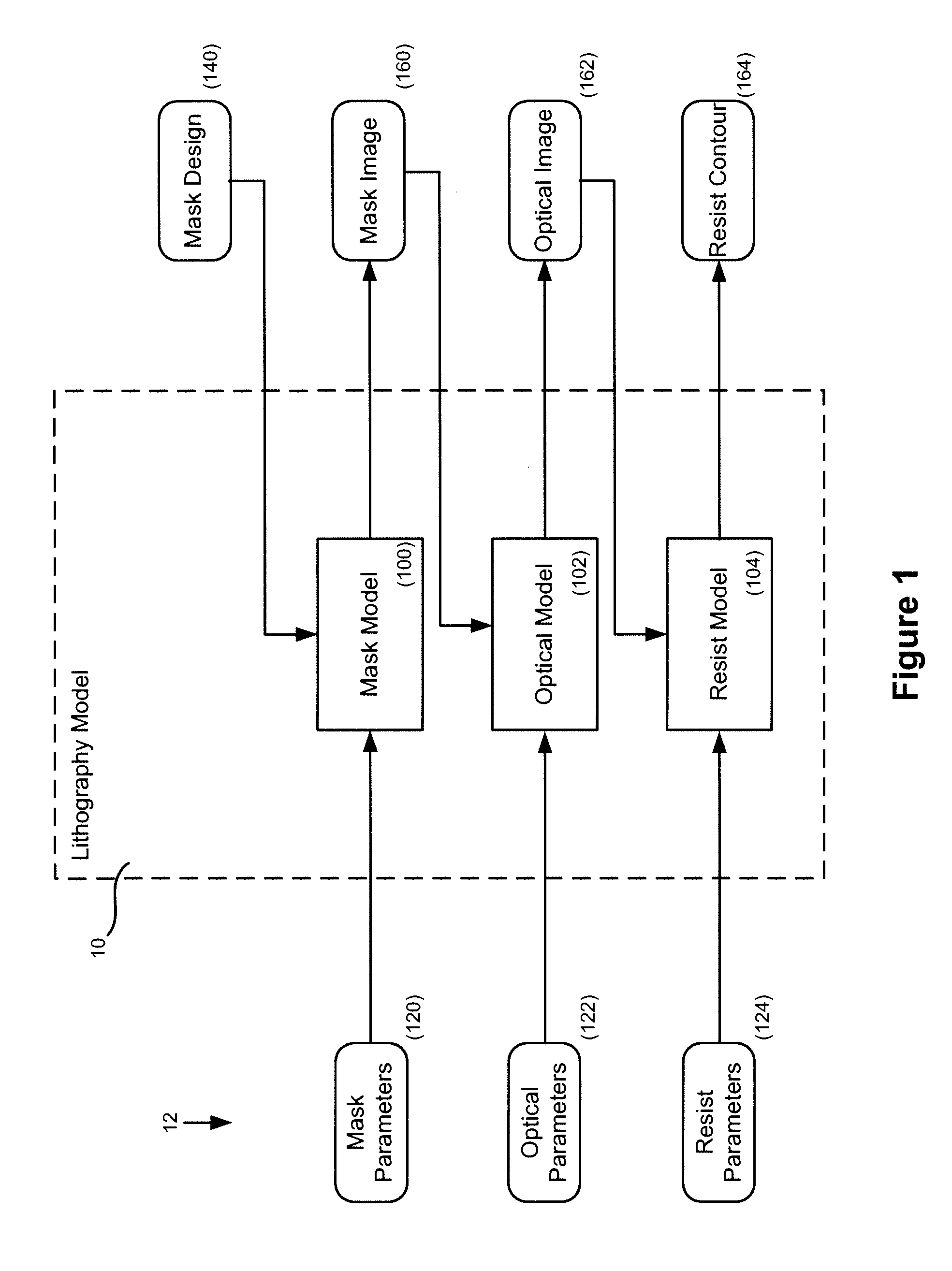
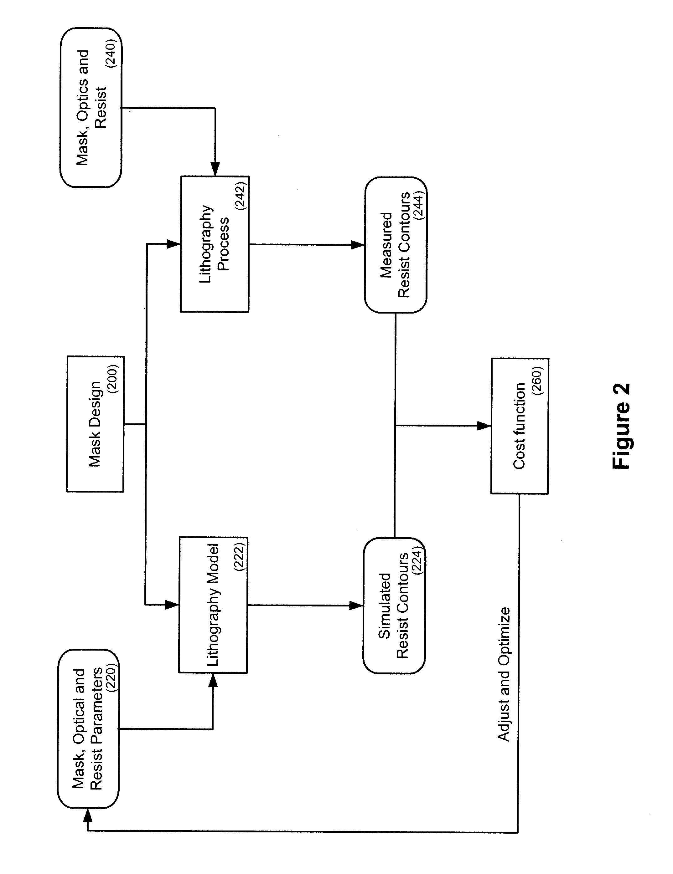
[0028]Embodiments of the present invention will now be described in detail with reference to the drawings, which are provided as illustrative examples so as to enable those skilled in the art to practice the invention. Notably, the figures and examples below are not meant to limit the scope of the present invention to a single embodiment, but other embodiments are possible by way of interchange of some or all of the described or illustrated elements. Wherever convenient, the same reference numbers will be used throughout the drawings to refer to same or like parts. Where certain elements of these embodiments can be partially or fully implemented using known components, only those portions of such known components that are necessary for an understanding of the present invention will be described, and detailed descriptions of other portions of such known components will be omitted so as not to obscure the invention. In the present specification, an embodiment showing a singular compon...


PUM

PropertyMeasurementUnit
Sensitivityaaaaaaaaaa

Abstract

Systems and methods for process simulation are described. The methods may use a reference model identifying sensitivity of a reference scanner to a set of tunable parameters. Chip fabrication from a chip design may be simulated using the reference model, wherein the chip design is expressed as one or more masks. An iterative retuning and simulation process may be used to optimize critical dimension in the simulated chip and to obtain convergence of the simulated chip with an expected chip. Additionally, a designer may be provided with a set of results from which an updated chip design is created.

Description


Claims


Application Information

Patent Timeline
Owner ASML NETHERLANDS BV
Learn More