Induction motor stator resistance and temperature parameter identifying method

A stator resistance and induction motor technology, applied in the field of testing, can solve problems such as the influence of the frequency conversion speed control system, and achieve the effect of improving system performance and saving use

Inactive Publication Date: 2010-07-21
SHANGHAI UNIVERSITY OF ELECTRIC POWER
View PDF0 Cites 56 Cited by
  • Summary
  • Abstract
  • Description
  • Claims
  • Application Information

AI Technical Summary

Problems solved by technology

[0003] The present invention is aimed at the problem that the change of stator resistance at low speed will affect the frequency conversion speed regulation system oriented according to the stator magnetic field, and proposes an i

Method used


Image

  • Induction motor stator resistance and temperature parameter identifying method
  • Induction motor stator resistance and temperature parameter identifying method
  • Induction motor stator resistance and temperature parameter identifying method

Examples


Embodiment Construction

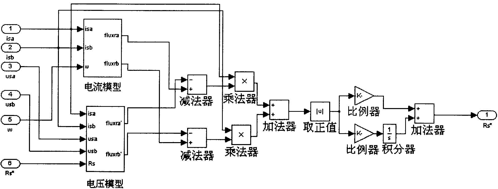
[0019] Two calculation models of motor rotor flux linkage - voltage model and current model. The current model is used as a reference model, and the voltage model is used as a regulation model.

[0020] The reference model is as follows:

[0021] P ψ rα ψ rβ = 1 τ r ( L m i sα i sβ - 1 τ r ω ...


PUM


Abstract

The invention relates to an induction motor stator resistance and temperature parameter identifying method. A control method based on model reference self-adaption is used for identifying the induction motor stator resistance and the stator winding temperature. According to the calculating method of an asynchronous motor rotor magnetic chain, the current magnetic chain calculating model is used as a reference model, a voltage magnetic chain calculating model is used as an adjusting model, and the output difference between the two models is used for continuously adjusting the stator resistance parameter in the voltage model through the self-adaption rate until the output difference of the two models is zero. The invention can effectively identify the stator resistance parameter and the stator winding temperature of the asynchronous motor in running, enhance the low-frequency property of the direct torque frequency-variable speed adjusting system of the asynchronous motor, eliminate the use of the temperature sensor, and save the cost of the speed adjusting system.

Description

technical field [0001] The invention relates to a testing method, in particular to a method for identifying stator resistance and temperature parameters of an induction motor. Background technique [0002] At present, frequency conversion speed regulation technology is gradually being widely used due to its good speed regulation performance and excellent energy-saving characteristics. High-performance frequency conversion speed regulation technology can be classified according to rotor field orientation, stator field orientation, and air gap field orientation. These speed control systems are all affected by motor parameters. For example, accurate estimation of stator flux linkage in stator field orientation technology is extremely important. When using the following flux linkage calculation model: ψ . s = ∫ ( U . s ...

Claims


Application Information

Patent Timeline
IPC IPC(8): H02P21/04G01R27/08G01K7/00
Inventor 梅柏杉陈晖梅菁汤凌峰
Owner SHANGHAI UNIVERSITY OF ELECTRIC POWER
Why Eureka
Try Eureka