Heat dissipation device

a heat dissipation device and electronic component technology, applied in semiconductor devices, lighting and heating apparatus, semiconductor devices, etc., can solve the problems of fan generation vibration when operating, adversely affecting the operation stability of electronic components, and generating large amounts of heat during normal operation

Inactive Publication Date: 2009-12-10
FU ZHUN PRECISION IND SHENZHEN +1
View PDF16 Cites 0 Cited by
  • Summary
  • Abstract
  • Description
  • Claims
  • Application Information

AI Technical Summary

Benefits of technology

[0005]Usually, a heat dissipation device is attached to a top surface of a CPU to dissipate heat therefrom. A typical heat dissipation device includes a heat sink attached to the CPU. The heat sink includes a plurality of fins. A fan is mounted on a top of the fins of the heat sink. It is known that the fan generates vibration when operating. The fins, on which the fan is mounted by a clip, will vibrate with the fan since the fan is directly attached thereto, whereby considerable noise is generated during operation.

Problems solved by technology

Computer electronic components, such as central processing units (CPUs), generate large amounts of heat during normal operation.
If the heat is not properly dissipated, it can adversely affect operational stability of the electronic components and damage associated electronic devices.
It is known that the fan generates vibration when operating.
The fins, on which the fan is mounted by a clip, will vibrate with the fan since the fan is directly attached thereto, whereby considerable noise is generated during operation.

Method used


Image

  • Heat dissipation device
  • Heat dissipation device
  • Heat dissipation device

Examples


Embodiment Construction

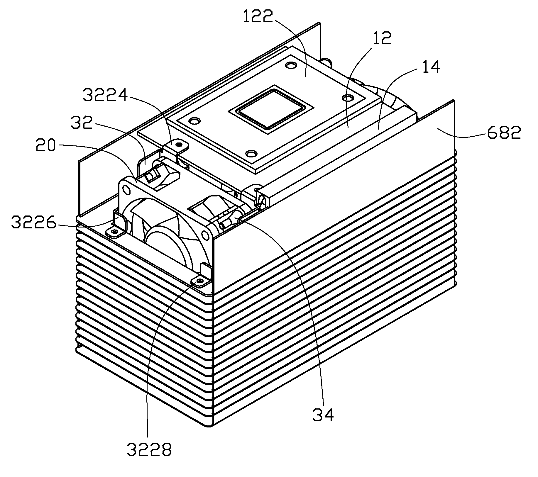
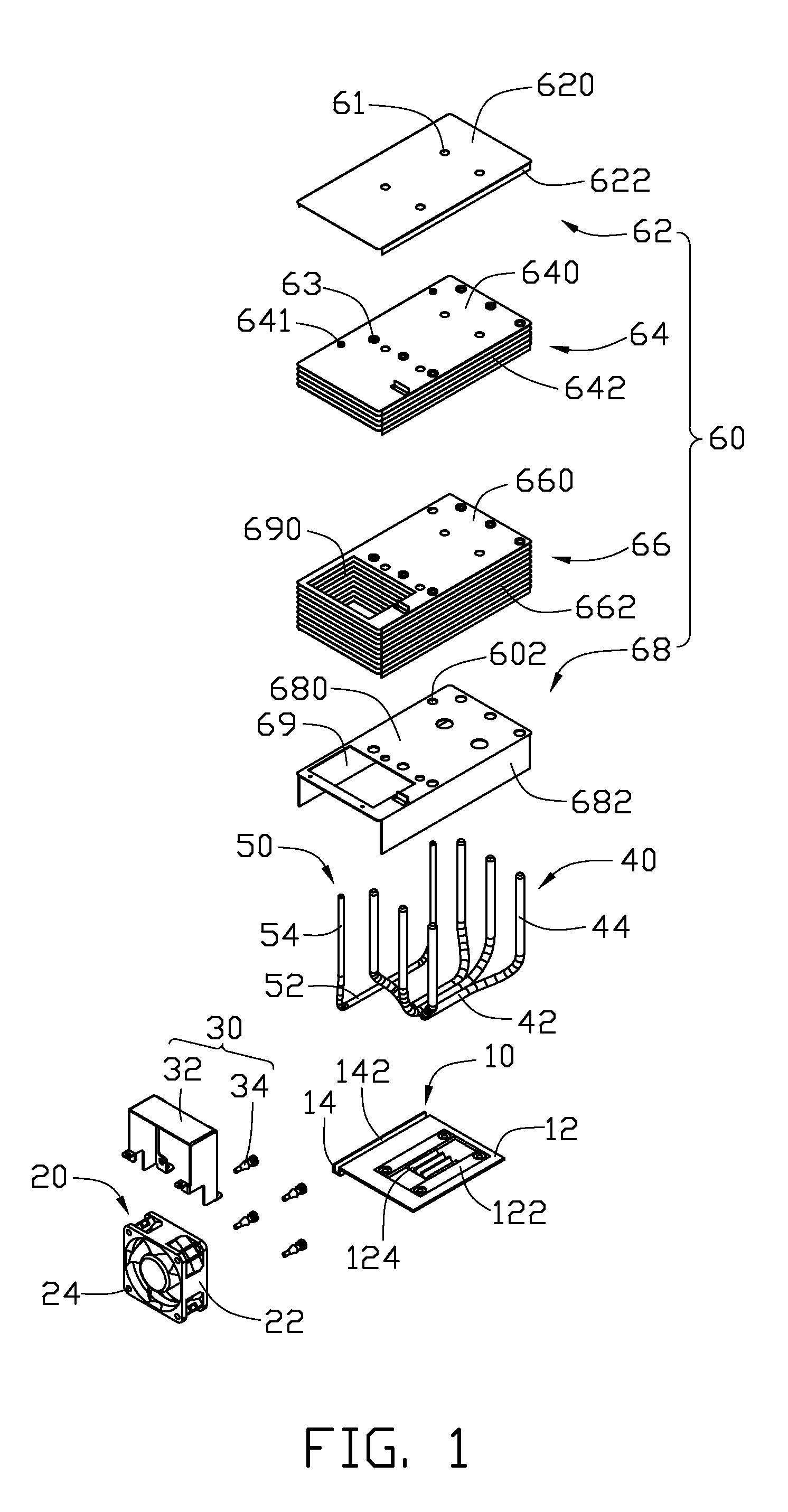
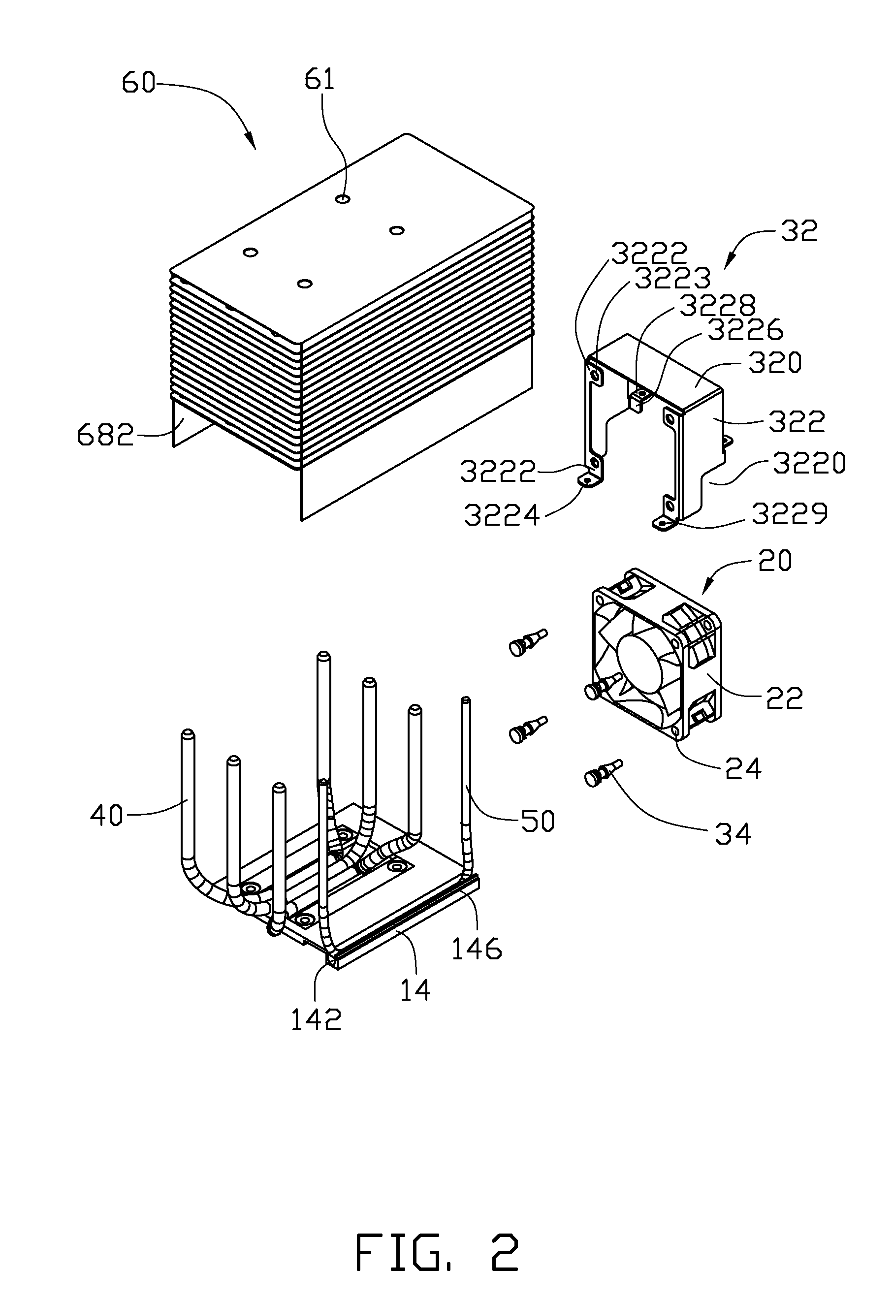
[0012]Referring to FIG. 1, a heat dissipation device in accordance with an embodiment of the disclosure dissipates heat generated by an electronic component (not shown), such as a CPU. The heat dissipation device comprises a substrate 10 attached to the electronic component, a fan 20 fixed on the substrate 10 by a securing device 30, a plurality of first heat pipes 40 and a second heat pipe 50, and a fin assembly 60 located on the substrate 10.

[0013]Also referring to FIG. 2, the substrate 10 comprises a substantially square main body 12, and a supporting bar 14 angles upwardly from a lateral side of the main body 12. A slot 142 is defined between the main body 12 and the supporting bar 14. A step 146 is formed on a top of the supporting bar 14. The main body 12 defines a rectangular hatch (not labeled) receiving a base 122 therein. The base 122 is near an opposite lateral side of the main body 12 and far from the supporting bar 14. A bottom surface of the base 122 is attached to the...


PUM


Abstract

A heat dissipation device includes a substrate, a fin assembly located on the substrate, a plurality of heat pipes connecting the substrate and the fin assembly, and a fan fixed on the substrate by a securing device. The securing device includes a holder fixed to the substrate and a plurality of elastic fasteners. The fasteners secure the fan onto the holder and each includes a sandwiched portion sandwiched between the fan and the holder to segregate the fan from the holder.

Description

BACKGROUND OF THE INVENTION [0001]1. Field of the Invention[0002]The present disclosure relates to heat dissipation for electronic components and, more particularly, to a heat dissipation device utilizing a fastener to fix a fan thereof.[0003]2. Description of Related Art[0004]Computer electronic components, such as central processing units (CPUs), generate large amounts of heat during normal operation. If the heat is not properly dissipated, it can adversely affect operational stability of the electronic components and damage associated electronic devices.[0005]Usually, a heat dissipation device is attached to a top surface of a CPU to dissipate heat therefrom. A typical heat dissipation device includes a heat sink attached to the CPU. The heat sink includes a plurality of fins. A fan is mounted on a top of the fins of the heat sink. It is known that the fan generates vibration when operating. The fins, on which the fan is mounted by a clip, will vibrate with the fan since the fan ...

Claims


Application Information

Patent Timeline
Patent Type & Authority Applications(United States)
IPC IPC(8): F28F7/00
CPCH01L23/3672H01L23/427H01L23/467H01L2924/0002H01L2924/00
Inventor LI, WEIWU, YI-QIANGCHEN, CHUN-CHI
Owner FU ZHUN PRECISION IND SHENZHEN
Why Eureka
Try Eureka