Guardrail

a technology of guardrails and rails, applied in the field of guardrails, can solve the problems of undesirable or unsafe effects, and achieve the effect of facilitating the dissipation of impact energy

Active Publication Date: 2009-12-10
VALMONT HIGHWAY TECH
View PDF80 Cites 21 Cited by
  • Summary
  • Abstract
  • Description
  • Claims
  • Application Information

AI Technical Summary

Benefits of technology

[0016]Preferably, during a collision or impact with the impact head the cable is forced through the cable gripping means, where resistance to cable movement substantially facilitates impact energy dissipation.

Problems solved by technology

However this gating effect may have undesirable or unsafe results, and preferably an improved or safer or varied energy absorbing system is utilised to control errant vehicle barrier / guardrail impacts.

Method used


Image

  • Guardrail
  • Guardrail
  • Guardrail

Examples


Embodiment Construction

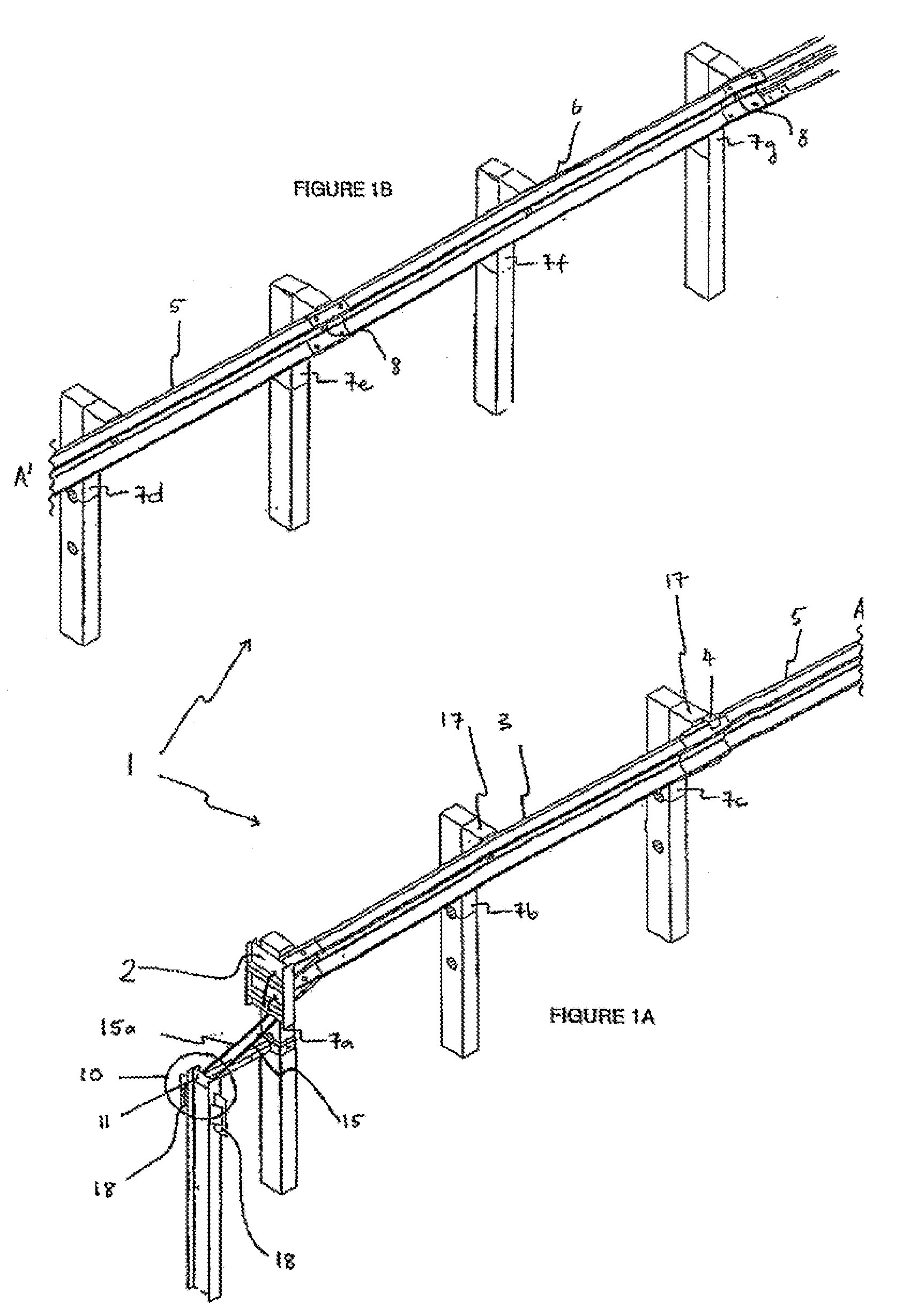
[0095]This invention is designed to be a substantially non-gating guardrail, meaning that at any point along the side of the guardrail from the terminal end onwards, an impacting vehicle on an angled collision may be substantially redirected away from its initial impact trajectory. It is also designed to substantially absorb energy during an end on impact to the terminal end.

[0096]“Gating” is a term used within the guardrail industry to refer to sections of guardrail which are unable to withstand high impact side angle collisions, and significant guardrail deformation or ultimate failure or breakage may occur.

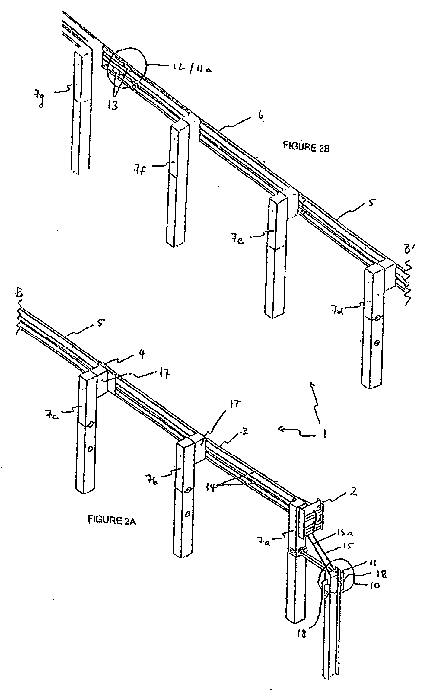
[0097]For the purposes of this illustrative description, FIGS. 1a and 1b will be referred together as FIG. 1; similarly FIGS. 2a and 2b will be referred to as FIG. 2. The guardrail 1 shown has been split into two sections for illustrative purposes only, and sections A and A′ in FIGS. 1a and 1b; and the same sections are labelled B and B′ in FIGS. 2a and 2b should be joined to s...


PUM


Abstract

An impact slider assembly for a guardrail which includes: a slider mechanism attached to a first rail and second rail which substantially conforms with a rail profile; and an integral means for attachment to the first rail, wherein the slider mechanism gathers telescoping rails whilst substantially maintaining the strength of the rails in a fully re-directing manner.

Description

CROSS REFERENCE TO RELATED APPLICATION[0001]This application claims the benefit of 35 U.S.C. §120 as a Continuation-in-Part of U.S. application Ser. No. 12 / 132,958, filed Jun. 4, 2008.TECHNICAL FIELD[0002]This invention relates to guardrails and in particular, though not solely, to guardrails and / or guardrail impact heads for use in roading networks and / or vehicle road lanes requiring separation by a barrier.BACKGROUND ART[0003]Existing highway guardrail end treatment systems include: the breakaway cable terminal (BCT), the eccentric loader terminal (ELT), the modified eccentric loader terminal (MELT), the vehicle attenuating terminal (VAT), the extruder terminal (ET 2000 and ET plus), the slotted rail terminal (SRT), the sequential kinking terminal (SKT) and the flared energy absorbing terminal (FLEAT).[0004]Terminal ends (that is, the end facing oncoming traffic) generally consist of one or more, often three, W shaped (in cross-section) guardrails supported by a series of both con...

Claims


Application Information

Patent Timeline
Patent Type & Authority Applications(United States)
IPC IPC(8): E01F15/00E01F15/02
CPCE01F15/025E01F15/143E01F15/06
Inventor JAMES, DALLAS
Owner VALMONT HIGHWAY TECH
Why Eureka
Try Eureka