Stepped grading spillway with energy dissipation effect

A ladder-shaped, spillway technology, applied in water conservancy projects, marine engineering, coastline protection, etc., can solve problems such as difficulty in achieving high energy dissipation effect, unstable water jump state of stilling pools, and lengthening of stilling pools. Achieve the effect of overcoming disadvantages and limitations of use conditions, structural safety and adaptability, and improving energy dissipation efficiency

Active Publication Date: 2022-03-01
CHINA POWER CONSRTUCTION GRP GUIYANG SURVEY & DESIGN INST CO LTD
View PDF3 Cites 2 Cited by
  • Summary
  • Abstract
  • Description
  • Claims
  • Application Information

AI Technical Summary

Problems solved by technology

[0003] However, there are certain applicable conditions and disadvantages in adopting the above two energy dissipation methods
The deflected flow energy dissipation mode is likely to cause the problem of flood discharge atomization, and the water tongue that is deflected to the downstream scours the riverbed water cushion to easily form scour pits. Generally, it is used under unavoidable conditions.
The bottom flow energy dissipation model is widely used. However, due to the constraints of topographical conditions and building layout, the high drop spillway (or spillway) has a large flow rate and concentrated energy. If the downstream water level is low, the hydraulic jump in the stilling basin may be unstable. Even the formation of a far drive hydraulic jump, insufficient energy dissipation, needs to be at the expense of lengthening the length of the stilling basin, even if energy dissipation measures are added in the stilling basin, it is difficult to achieve a high energy dissipation effect

Method used


Image

  • Stepped grading spillway with energy dissipation effect
  • Stepped grading spillway with energy dissipation effect
  • Stepped grading spillway with energy dissipation effect

Examples


Embodiment Construction

[0030] The technical solution of the present invention is further described below, but the scope of protection is not limited to the description.

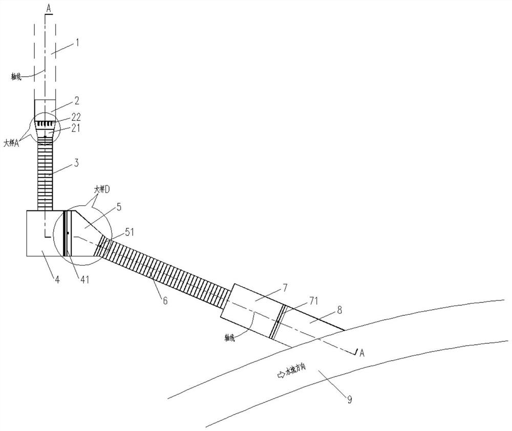
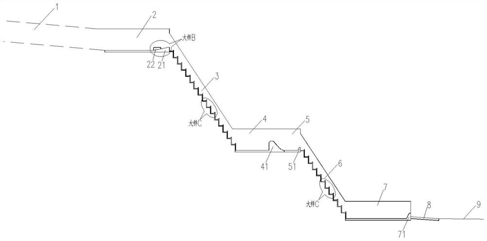
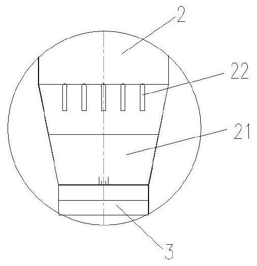
[0031] Such as Figure 1 to Figure 6 As shown, a ladder-shaped graded spillway with energy dissipation effect according to the present invention includes a first-level stilling basin 2, a first-level steep groove 3, a second-level stilling basin 4, and a third-level stilling basin arranged in sequence from upstream to downstream Stilling basin 5, second-level steep groove 6, fourth-level stilling basin 7 and sea diffuser 8, the upstream side of the first-level stilling basin 2 is connected to the flood discharge tunnel 1, and the downstream side of the said sea diffuser 8 is connected to the original The river course 9 connects smoothly. When in use, the transverse direction of the first-level stilling pool 2, the first-level steep groove 3, the second-level stilling pool 4, the third-level stilling pool 5, the second-level steep ...


PUM


Abstract

The invention discloses a stepped graded spillway with an energy dissipation effect, and belongs to the technical field of water conservancy and hydropower building engineering. The spillway comprises a first-stage stilling pool, a first-stage chute, a second-stage stilling pool, a third-stage stilling pool, a second-stage chute, a fourth-stage stilling pool and an apron which are sequentially arranged from upstream to downstream, the upstream side of the first-stage stilling pool is connected with a flood discharge tunnel, and the downstream side of the apron is smoothly connected with an original river channel. The spillway is arranged at an outlet of the spillway tunnel, and spillway water flows through the multi-stage stilling pool and the multi-stage chute to fully dissipate energy and then is discharged into an original river channel, so that scouring to the original river channel is relieved, and the safety of downstream buildings is guaranteed; meanwhile, due to the fact that the first-stage stilling pool, the first-stage chute, the second-stage stilling pool, the third-stage stilling pool, the second-stage chute and the fourth-stage stilling pool are each of a closed structure in the transverse direction, flood discharge atomization can be prevented from being caused in the energy dissipation process.

Description

technical field [0001] The invention relates to a stepped spillway with energy dissipation effect and belongs to the technical field of water conservancy and hydropower construction engineering. Background technique [0002] In water conservancy and hydropower projects, generally, the energy of the water flowing out of the outlet of the spillway (or spillway) is relatively large, and the downstream riverbed is subjected to a large scouring force, which has a great impact on the riverbed and its surrounding environment, especially when it is arranged on a high and steep mountain. The problem of energy dissipation at the outlet of the spillway tunnel is particularly prominent. Flood discharge and energy dissipation is a crucial link in the design of water conservancy and hydropower projects. In order to ensure the safety of buildings and reduce the erosion of downstream rivers, energy dissipation devices are usually installed in discharge structures to connect upstream and dow...

Claims


Application Information

Patent Timeline
Patent Type & Authority Applications(China)
IPC IPC(8): E02B8/06
CPCE02B8/06
Inventor 文浩刘曜秦晓亮王明房彬吕康王杰罗佩玉
Owner CHINA POWER CONSRTUCTION GRP GUIYANG SURVEY & DESIGN INST CO LTD
Why Eureka
Try Eureka