
Beltless tandem-type image forming apparatus

a technology of image forming apparatus and beltless technology, which is applied in the direction of electrographic process, instruments, transportation and packaging, etc., can solve the problems of image noise such as color drift and transfer shift on the sheet, and achieve the effect of sufficient image formation

Active Publication Date: 2009-12-10
KONICA MINOLTA BUSINESS TECH INC
View PDF3 Cites 2 Cited by
  • Summary
  • Abstract
  • Description
  • Claims
  • Application Information

AI Technical Summary

Benefits of technology

[0006]Accordingly, an object of the present invention is to provide a beltless tandem-type image forming apparatus capable of preventing image noise such as color drift and transfer shift on a sheet from being generated even if the conveying speed varies among respective pairs of transfer rollers.
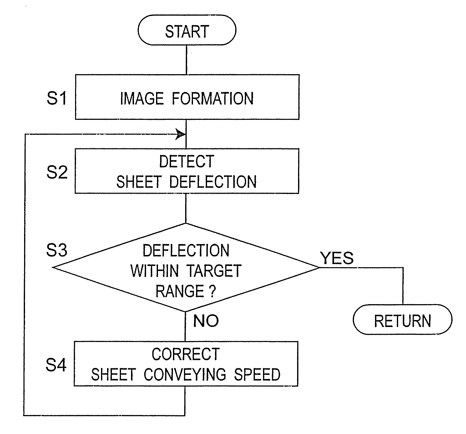
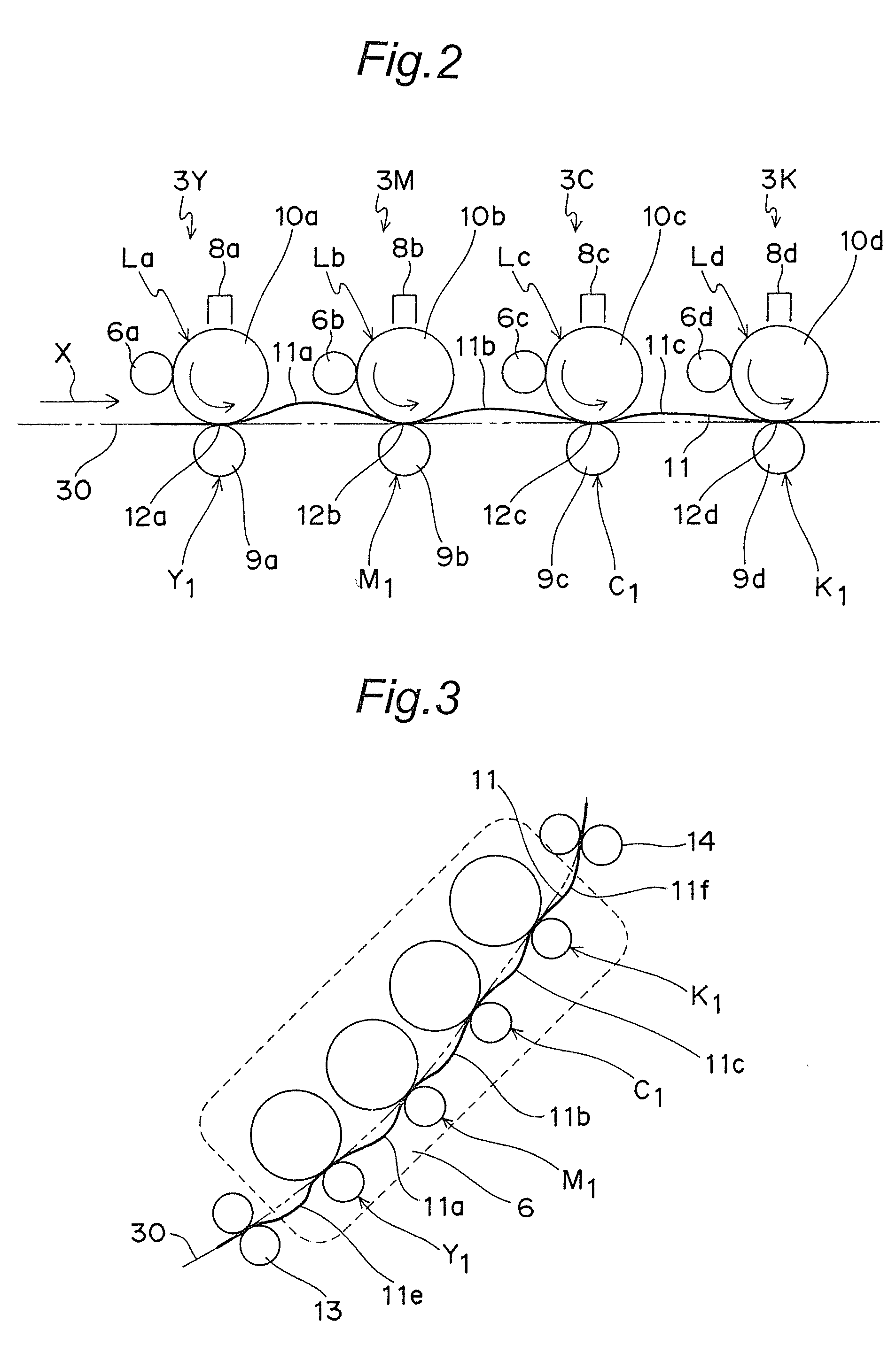
[0016]In view of downsizing the apparatus, the tandem-type image forming apparatus is generally structured so that a plurality of the pairs of transfer rollers are often placed in a region shorter than or equal to the length of the conveying direction of one sheet. Accordingly, at least the pairs of transfer rollers which are adjacent to each other, among a plurality of the pairs of transfer rollers, are to be placed in a region shorter than the length of the conveying direction of the sheets. In such a case, in the image forming apparatus of the invention, deflection is generated on the sheet in the direction vertical to the conveying direction of the sheet depending on a difference in conveying speed between the pairs of transfer rollers which are adjacent to each other in a region between the pairs of transfer rollers adjacent to each other along the conveying direction of the sheets when the sheets are sequentially conveyed through the nip sections composed of the respective pairs of transfer rollers. Therefore, even if the conveying speed of the respective pairs of transfer rollers varies when the sheets are conveyed, it becomes possible to prevent one sheet from being pulled in different direction at the same time. As a result, the problem of image noise such as color drift and transfer shift on the sheet may be prevented from arising.
[0017]The conveying speeds of the respective pairs of transfer rollers controlled by the driving section are gradually decreased for every pair of transfer rollers from an upstream side toward a downstream side along the conveying direction of the sheets, and consequently, a driving period for driving the respective pairs of transfer rollers to convey each sheet is gradually increased for every pair of transfer rollers from the upstream side toward the downstream side along the conveying direction of the sheets. If, as in general tandem-type image forming apparatuses, the length of the imaging period by the imaging section is the same among the respective pairs of transfer rollers, the imaging period by the imaging section and the driving period by the driving section become out of synchronization in a certain pair of transfer rollers. Accordingly, the control section performs control so that the imaging period by the imaging section is synchronized with the driving period by the driving section in every pair of transfer rollers. This achieves sufficient image formation on the sheets.

Problems solved by technology

As a result, a problem of image noise such as color drift and transfer shift on the sheet may arise.

Method used


Image

  • Beltless tandem-type image forming apparatus
  • Beltless tandem-type image forming apparatus
  • Beltless tandem-type image forming apparatus

Examples


Embodiment Construction

[0028]Hereinbelow, the present invention will be described in details in conjunction with the embodiments with reference to the drawings.

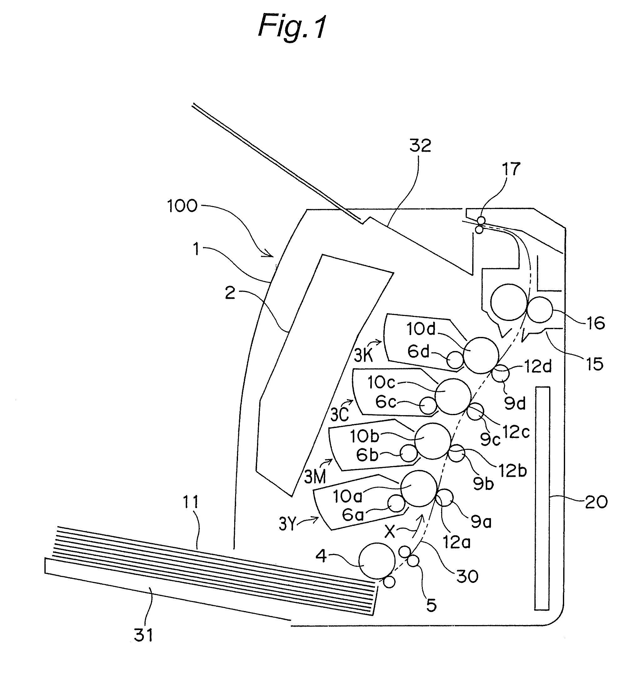
[0029]FIG. 1 is a schematic cross sectional structure view of a beltless color tandem-type image forming apparatus 100 in one embodiment of the invention. The image forming apparatus 100 is structured so that four cartridge-type image forming units 3Y, 3M, 3C and 3K detachable from a main body casing 1 are placed side by side at intervals in generally the center within the main body casing 1 along a conveying direction X of paper sheets 11 as sheets (a conveying path is shown with a two-dot chain line 30), more specifically from the upstream side (lower side in FIG. 1) to the downstream side (upper side in FIG. 1). The four image forming units 3Y, 3M, 3C and 3K are for transferring toner images of four colors: yellow; magenta; cyan; and black, onto the paper sheets 11 by the electrophotographic method.

[0030]In this example, in view of downsizing th...


PUM


Abstract

In a beltless tandem-type image forming apparatus of the invention, a plurality of pairs of transfer rollers are placed side by side at intervals along a conveying direction of sheets. A control section independently conveys sheets in sequence through nip sections of respective pairs of transfer rollers driven by a driving section while sequentially transferring images formed by an imaging section onto the sheets. Conveying speeds of the respective pairs of transfer rollers controlled by the driving section are gradually decreased for every pair of transfer rollers from an upstream side toward a downstream side along a conveying direction of the sheets, and consequently, a driving period for driving the respective pairs of transfer rollers to convey each sheet is gradually increased for every pair of transfer rollers from the upstream side toward the downstream side along the conveying direction of the sheets. The control section performs control so that an imaging period by the imaging section is synchronized with a driving period by the driving section in every pair of transfer rollers.

Description

TECHNICAL FIELD[0001]The present invention relates to a beltless tandem-type image forming apparatus. The beltless tandem-type image forming apparatus herein refers to a type of image forming apparatus in which a plurality of pairs of an image carrier roller and an opposed roller which is brought into pressure contact with the image carrier roller are placed side by side at intervals for conveying sheets independently through nip sections formed from the respective pairs so that images formed on the surfaces of the image carrier rollers are sequentially transferred onto the sheets.BACKGROUND ART[0002]As the tandem-type image forming apparatus, there is known an apparatus (of direct transfer method) in which four image forming means (hereinafter referred to as “image forming units”) each including a pair of a photoconductor drum and a roller which is brought into pressure contact with the photoconductor drum (hereinafter referred to as “a pair of transfer rollers”) are placed side by...

Claims


Application Information

Patent Timeline
Patent Type & Authority Applications(United States)
IPC IPC(8): B65H7/02
CPCG03G15/0131G03G2215/0158G03G2215/0138
Inventor KATOGI, SYUICHIYOSHIKAWA, SHOICHIMORO, FUMINORIITO, TAKAYUKIKAWAI, MASASHIOOMOTO, NOBORU
Owner KONICA MINOLTA BUSINESS TECH INC
Learn More