Door stop

a technology for doors and stops, applied in the direction of fastening means, carpet fasteners, mechanical devices, etc., can solve the problems of difficulty in maneuvering, various deficiencies of door stops, and awkwardness,

Inactive Publication Date: 2009-12-10
DANIEL FRITZ
View PDF17 Cites 8 Cited by
  • Summary
  • Abstract
  • Description
  • Claims
  • Application Information

AI Technical Summary

Problems solved by technology

While suitable for many purposes, these doorstops suffer various deficiencies.
Such maneuvers are sometimes difficult and awkward.

Method used


Image

  • Door stop
  • Door stop
  • Door stop

Examples


Embodiment Construction

[0016]An apparatus is described for operating as a doorstop. In the following description, for the purposes of explanation, numerous specific details are set forth in order to provide a thorough understanding of the present invention. It will be apparent, however, to one skilled in the art that the present invention may be practiced without these specific details. In other instances, well-known structures and devices are shown in block diagram form in order to avoid unnecessarily obscuring the present invention.

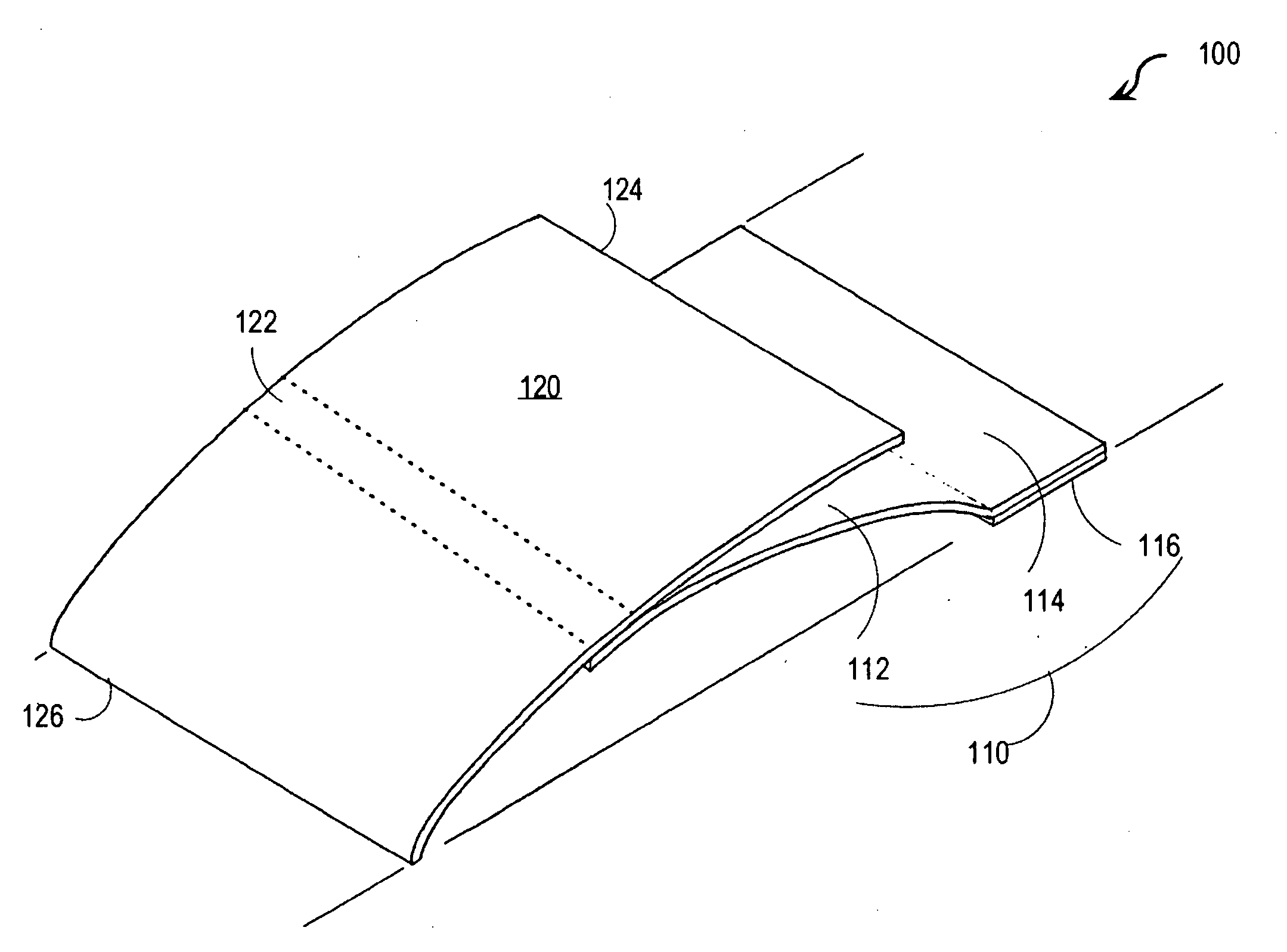
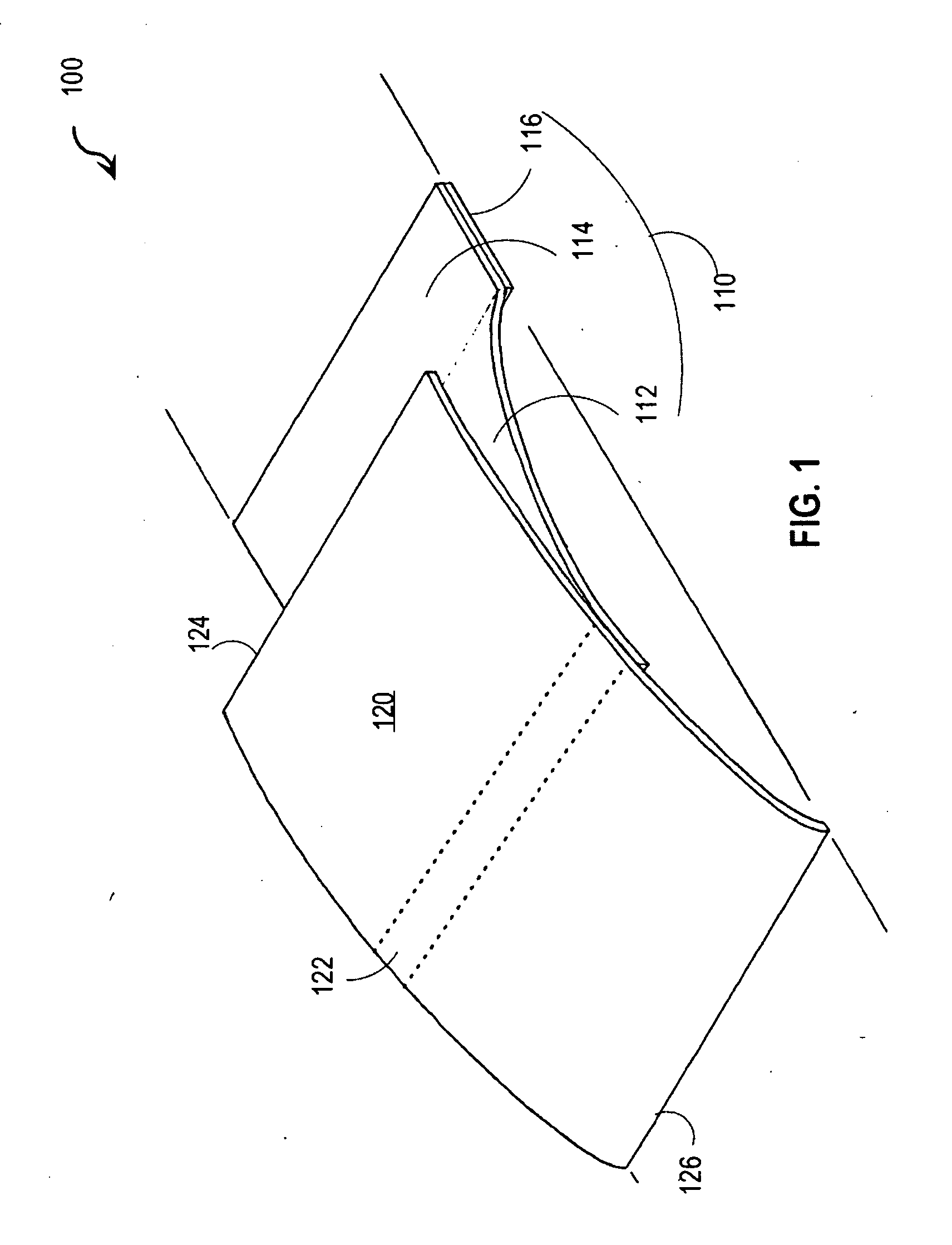
[0017]FIG. 1 is a perspective drawing that illustrates a doorstop 100, according to an embodiment. The doorstop 100 is depicted deployed on a horizontal floor indicated in FIG. 1 by diagonal lines; however, the floor is not part of the doorstop 100.

[0018]The doorstop includes a spring member 110 and a flange 120. The spring member 110 includes an arc-shaped portion 112 having a rest curvature and a floor contacting end portion 114 that is flat. The flange 120 includes a door-...


PUM


Abstract

A doorstop includes a flange connected to a floor contacting portion. The flange is deflectable under transverse pressure. During operation, a door-engaging end portion of the flange contacts a vertical face of a door. Upon deflection, the end portion drops below the vertical face to allow the door to close. In some embodiments, a doorstop includes a spring member and a flange. The spring member includes an arc-shaped portion having a rest curvature and a floor contacting end portion. The arc-shaped portion is deflectable to an arc with less curvature under transverse pressure and returns to the rest curvature upon removal of the transverse pressure. The flange includes a door-engaging end portion and a different attached portion. The attached portion is attached to the arc-shaped portion of the spring member such that the flange is substantively tangent to the arc-shaped portion of the spring member along the attached portion.

Description

CROSS-REFERENCE TO RELATED APPLICATIONS[0001]This application claims benefit of Provisional Appln. 61 / 059,779, filed Jun. 8, 2008 under 35 U.S.C. §119(e).BACKGROUND OF THE INVENTION[0002]1. Field of the Invention[0003]The present invention relates to door stops, and in particular to a door stop with a extended flange deflectably mounted to engage a door to be stopped.[0004]2. Description of the Related Art[0005]A number of door stops have been described in the art, each with some advantage in terms of manufacturing or footprint or portability or ease of use without requiring a user to bend down and manually move a device in place every time a door is opened. For example, spring action door stops described in U.S. patent Ser. No. 4,044,424 to A. Sasgen (hereinafter Sasgen) and U.S. patent Ser. No. 5,331,719 to T. Hum (hereinafter Hum) work by applying pressure on the underside of a door when the door is positioned over the device. While suitable for many purposes, these doorstops suf...

Claims


Application Information

Patent Timeline
Patent Type & Authority Applications(United States)
IPC IPC(8): E05C17/54
CPCE05C17/54E05C17/52Y10S292/15Y10T292/73
Inventor FRITZ, DANIEL W.
Owner DANIEL FRITZ
Why Eureka
Try Eureka