Apparatus and methods for transferring workpiece in a transfer press machine

a technology of transfer press machine and workpiece, which is applied in the direction of forging presses, metal-working feeding devices, manufacturing tools, etc., can solve the problems of difficult problems and inability to transfer workpieces easily

Inactive Publication Date: 2000-08-29
IHI CORP
View PDF4 Cites 9 Cited by
  • Summary
  • Abstract
  • Description
  • Claims
  • Application Information

AI Technical Summary

Problems solved by technology

Consequently, the position of the rack has to be adjusted during the lifting operation, through a complicated correcting operation, which has been a difficult problem in practice.
Therefore, the vertical rod 39 cannot slide smoothly...

Method used


Image

  • Apparatus and methods for transferring workpiece in a transfer press machine
  • Apparatus and methods for transferring workpiece in a transfer press machine
  • Apparatus and methods for transferring workpiece in a transfer press machine

Examples


first embodiment

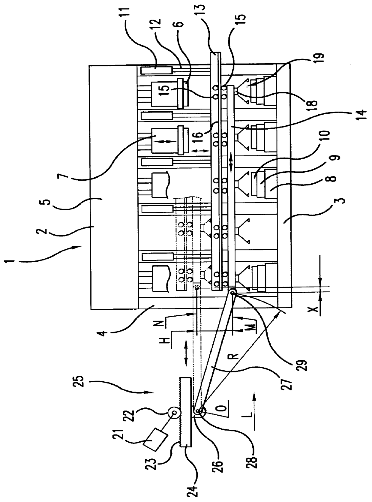
FIG. 3 is a view showing the general configuration of an apparatus for transferring and moving workpieces in a transfer press machine, according to the present invention. FIG. 4 is an enlarged view showing the operating direction changeover mechanism of the present invention.

The apparatus shown in FIG. 3 is a transfer press machine of the servo motor driven type with the same configuration as that shown in FIG. 1. In FIG. 3, an apparatus for transferring and moving workpieces according to the present invention is composed of upper and lower dies 6, 10 in a main press unit 2, at predetermined intervals along a press line L for continuously pressing and processing workpiece, a pair of lift beams 13 arranged opposite each other and parallel to the press line L on both sides of the dies and capable of being freely raised and lowered, workpiece holders 19 from which the workpieces are hung and which deliver the workpieces to and remove them from the lower dies 10, cross bars 18 that hold...

second embodiment

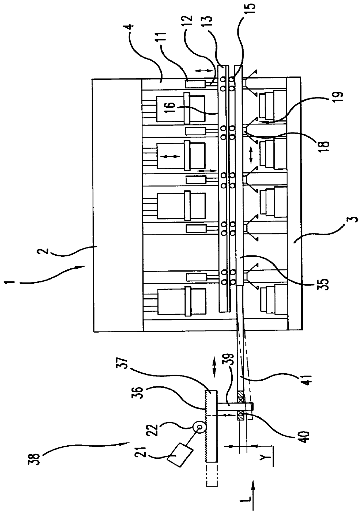
FIG. 5 is an enlarged view showing the operation direction changeover mechanism 70 of the apparatus for transferring and moving the workpiece in a transfer press machine according to the present invention.

The horizontal guide device 71 of the present invention is composed of a horizontal guide unit 75 mounted on the rack beam 73 on the opposite side to the rack 74 in the feed and transfer device 72, a long slot 76 provided in the horizontal guide unit 75 and extending in the direction of the press line L, and a roller-shaped rotating shaft unit 78 attached to the tip of the connecting rod 77 on the feed beam 14 side and provided with a built-in bearing, not illustrated and guided by the long slot 76 so that it can move freely in the direction of the press line L. Also using this system, unwanted differential movement caused by the curvature of the press transfer motion, produced in the feed beam 14 in synchronism with the raising and lowering of the lift beam 13, can be easily conve...

third embodiment

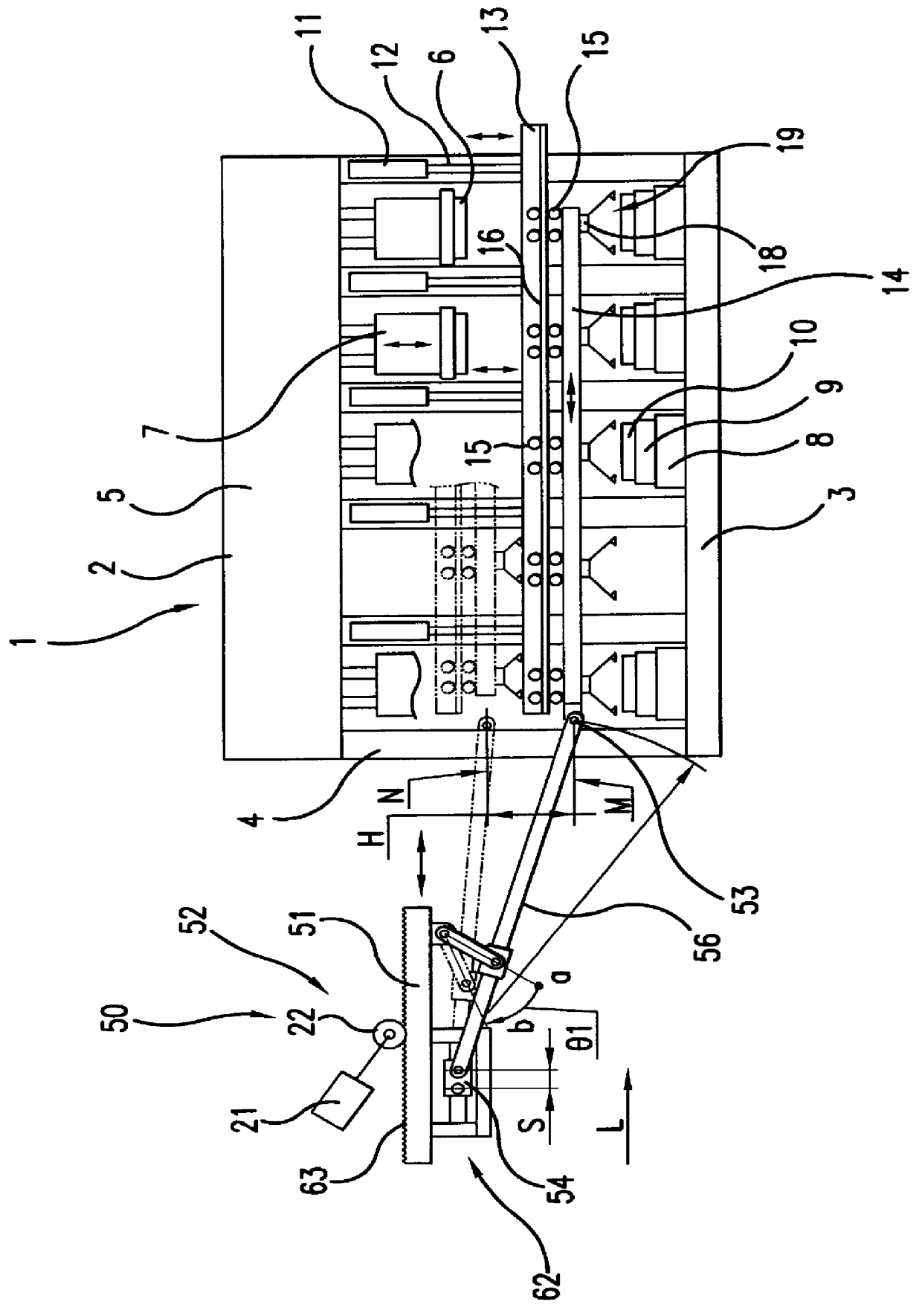
FIG. 6 shows a general configuration of the apparatus for transferring and moving the workpiece in a transfer press machine according to the present invention. FIG. 7 is an enlarged view of the operating direction changeover mechanism of the present invention.

In FIGS. 6 and 7, the operating direction changeover mechanism 81 of the apparatus 80 for transferring and moving the workpiece according to the present invention is a link mechanism 83 provided in the feed and transfer device 82. The link mechanism 83 is provided with a bracket 86 mounted on the rack beam 84 on the opposite side to the rack 85 in the feed and transfer device 82, and a changeover link 88 connecting the bracket 86 to the tip of the connecting rod 87 on the opposite side to the feed beam 14 in such a manner that the changeover, link 88 can freely rotate in the direction of the press line L. In addition, a bracket 89 is installed on the rack beam 84 on the opposite side to the rack 85 to which a connecting link 90...


PUM


Abstract

Cross bars 18, to which workpiece holders 19 are attached, are provided across a press line L, together with feed beams 14 between which the cross bars are installed and which are suspended from the lift beams 13 and can move freely in the horizontal direction of the press line. A feed and transfer device 52 can move the feed beams freely in the horizontal direction of the press line. A connecting rod 56 connects the feed beams and the rack beam in a freely rotatable manner. A connecting link 60 connects a point in the vicinity of an intermediate portion of the connecting rod to a bracket 58 installed on the rack beam, in a freely rotatable manner. An operating direction changeover mechanism 61 converts the differential movement caused by the curvature of the press transfer motion, produced in the feed beams when the lift beams are raised or lowered, into a horizontal movement in the direction of the press line in synchronism with the raising or lowering of the lift beams.

Description

1. Technical Field of the BackgroundThe present invention relates to an apparatus and methods for transferring the workpiece in a transfer press machine, in which the operation of transferring the workpiece is carried out by a combination of a rack and pinion, etc.2. Prior ArtA conventional transfer press machine known in the prior art uses a system with a cam mechanism in which the dies are driven up and down in synchronism with the transfer of the workpiece. Recently, however, a system using a combination of a servo motor and a rack and pinion drive, etc., has been proposed to replace the system with a cam mechanism for transferring the workpiece, because there has been a demand for higher operating speeds in transfer press machines.FIG. 1 is a schematic view showing such an example of a conventional system. In the transfer press machine 1, a main press unit 2 is configured with a bed 3 arranged along a press line L, a specified number of uprights 4 located opposite each other alo...

Claims


Application Information

Patent Timeline
IPC IPC(8): B21D43/05B30B13/00
CPCB21D43/055B65G49/00
Inventor YOSHII, EIICHIIURA, TAKAOTAKAHASHI, YOSHIOMORI, YOSHIOHASHIZUME, TAKEO
Owner IHI CORP
Why Eureka
Try Eureka