
Alerting device with supervision

a technology of alerting device and supervision, which is applied in the direction of repeater circuits, frequency-division multiplexes, instruments, etc., can solve the problems of increasing initial cost and ongoing maintenance costs, limiting the scope of application, and increasing the overall complexity of the system, so as to reduce the stress and fatigue of antennas, reduce stress and fatigue, and minimize stress and fatigue.

Active Publication Date: 2009-12-10
SILENT CALL CORP
View PDF4 Cites 93 Cited by
  • Summary
  • Abstract
  • Description
  • Claims
  • Application Information

AI Technical Summary

Benefits of technology

"The present patent is about an improved alerting system for the disabled, specifically for alerting individuals who are deaf, blind, or otherwise impaired. The system uses a monitoring device that sends signals to a reporting station when a predetermined condition is detected. The monitoring device is portable and can be used in different locations. The system also includes a control circuit, a visual display, and a charger device. The technical effects of this patent are that it provides a more comprehensive and portable alerting system for the disabled, and it ensures that communication is always positive between the monitoring device and the reporting station."

Problems solved by technology

While the aforementioned alarm systems are useful for their intended purpose, it should be appreciated that they are limited to a certain location by their physical constraints.
Moreover, because of their reduced portability, it is often necessary to employ multiple reporting stations throughout a building to permit a moving user to be confident that they will be within range to hear, see, or otherwise be stimulated in response to an alert.
This often requires the purchase, setup, and maintenance of reporting stations in each of the main rooms of a home or business, thereby increasing initial costs and ongoing maintenance costs and likewise adding to the overall complexity of the system.

Method used


Image

  • Alerting device with supervision
  • Alerting device with supervision
  • Alerting device with supervision

Examples


Embodiment Construction

[0020]Example embodiments are provided so that this disclosure will be thorough, and will fully convey the scope to those who are skilled in the art. Numerous specific details are set forth such as examples of specific components, devices, and methods, to provide a thorough understanding of embodiments of the present disclosure. It will be apparent to those skilled in the art that specific details need not be employed, that example embodiments may be embodied in many different forms and that neither should be construed to limit the scope of the disclosure.

[0021]The terminology used herein is for the purpose of describing particular example embodiments only and is not intended to be limiting. As used herein, the singular forms “a”, “an” and “the” may be intended to include the plural forms as well, unless the context clearly indicates otherwise. The terms “comprises,”“comprising,”“including,” and “having,” are inclusive and therefore specify the presence of stated features, integers,...


PUM


Abstract

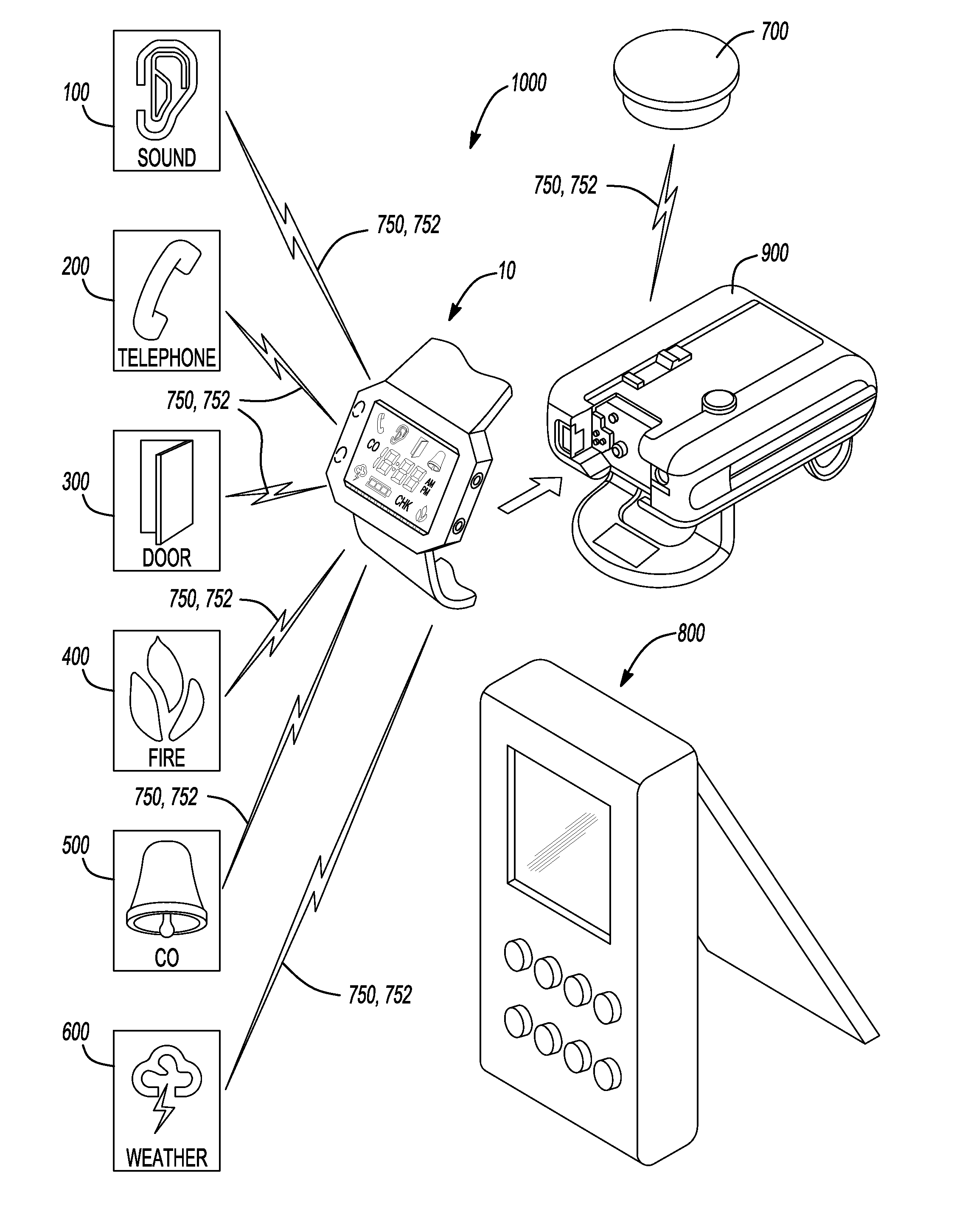
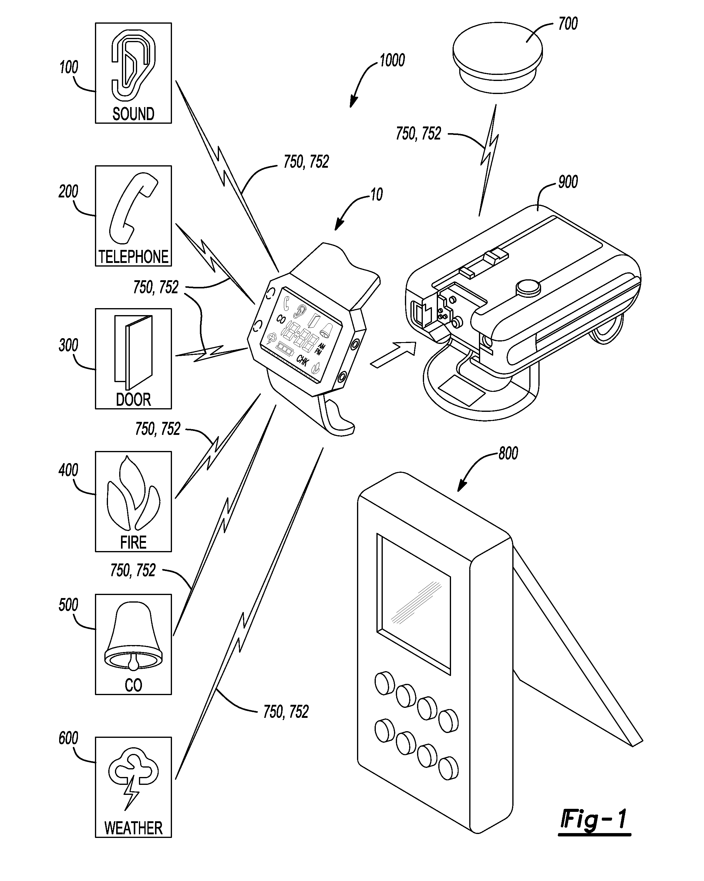
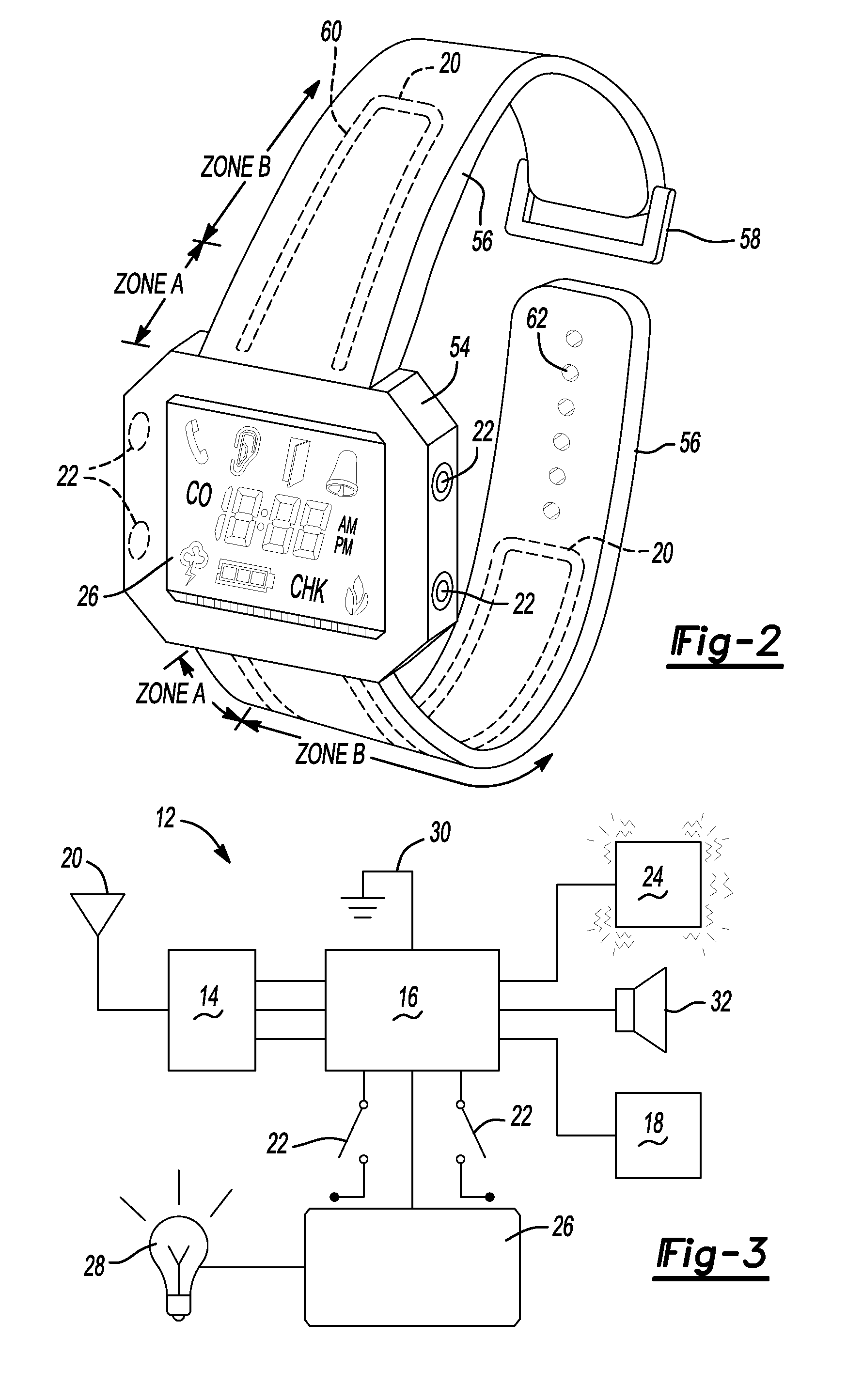
An alerting system for alerting a user having a transmitter monitoring a predetermined condition (i.e. sound, telephone, door / window access, fire, carbon monoxide, emergency weather alerts, etc.) and outputting an alarm signal in response to detection of the predetermined condition. The transmitter further outputs a supervisory signal indicative of operation of the transmitter (i.e. low battery condition, out of range, etc.). The alerting system further includes an alerting device receiving the alarm signal and the supervisory signal from the transmitter and detecting cessation of the supervisory signal device and outputting a first alert signal to the user indicative of the cessation of the supervisory signal. The alerting device further detecting presence of the alarm signal and outputting a second alert signal to the user indicative of presence of the predetermined condition.

Description

CROSS-REFERENCE TO RELATED APPLICATIONS[0001]This application claims the benefit of U.S. Provisional Application No. 61 / 060,302, filed on Jun. 10, 2008. The entire disclosure of the above application is incorporated herein by reference.FIELD[0002]The present disclosure relates to alerting devices for the disabled and, more particularly, relates to alerting devices having supervisory capability for monitoring transmitters and communications therewith.BACKGROUND AND SUMMARY[0003]This section provides background information related to the present disclosure which is not necessarily prior art. This section also provides a general summary of the disclosure, and is not a comprehensive disclosure of its full scope or all of its features.[0004]As is well known in the art, alarm systems are readily available for use by handicapped users, such as those that are blind, deaf, or otherwise impaired, to alert the handicapped user of some predetermined condition, such as a doorbell, telephone, or ...

Claims


Application Information

Patent Timeline
Patent Type & Authority Applications(United States)
IPC IPC(8): G08B23/00H04B3/36
CPCG08B25/10G08B25/14G08B29/14G08B29/145
Inventor STROHALLEN, GENE MICHAELELWELL, GEORGE J.
Owner SILENT CALL CORP
Learn More