Light engine system for reflective liquid crystal projection display

A liquid crystal projection and reflection technology, applied in the field of light engine system, can solve the problem of not improving the efficiency of the whole machine, and achieve the effect of increasing the complexity of the system, improving the optical efficiency and the overall brightness, and maximizing the utilization rate of light.

Active Publication Date: 2011-11-02
SHENZHEN EVIEWTEK TECH CO LTD
View PDF7 Cites 17 Cited by
  • Summary
  • Abstract
  • Description
  • Claims
  • Application Information

AI Technical Summary

Problems solved by technology

[0007] In view of the fact that none of the existing micro-projection light engines can fundamentally improve the efficiency of the whole machine to increa

Method used


Image

  • Light engine system for reflective liquid crystal projection display
  • Light engine system for reflective liquid crystal projection display
  • Light engine system for reflective liquid crystal projection display

Examples


Example Embodiment

[0034] Example 1

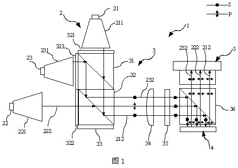
[0035] figure 1 The first embodiment of the present invention for the reflective liquid crystal projection display system 1 is given, which includes a light source module 2, a polarization management module 3, an image information module 4 and a projection lens 5.

[0036] The light source module 2 includes a red light LED 21, a green light LED 22, a blue LED 23, a red light homogenizing device 211, a green light homogenizing device 221, and a blue light homogenizing device 231. The red LED 21 and the red light homogenizing device 211 are connected, The green LED 22 is connected to the green light homogenizing device 221, and the blue LED 23 is connected to the blue light homogenizing device 231.

[0037] The natural light of the three primary colors emitted by the red light LED 21, the green light LED 22, and the blue light LED 23 is collected into a small-angle rectangular beam required for illumination after passing through a red light homogenizing device 211, a...

Example Embodiment

[0049] Example 2

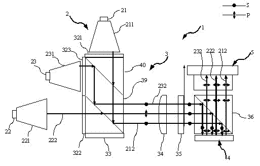
[0050] image 3 A second example of the present invention is given. Compared with the first example, in the polarization color combination unit of the second example, a parallelogram prism 39 is used to glue two first right-angle prisms 40 instead of the dichroic prism 31 and the first PBS, and the parallelogram prism One color combination surface of 39 is coated with a dichroic film and then a first right-angle prism 40 is glued, and the other color surface of the parallelogram prism 39 is coated with a polarization beam splitting film and then a first right-angle prism 40 is glued. The advantage is that the interface between the dichroic prism 31 and the first PBS 32 is reduced, which is more conducive to the integration of the optical system.

Example Embodiment

[0051] Example 3

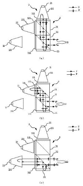
[0052] Figure 4 A third example of the present invention is given. This instance is different from figure 1 The example is that in the polarization combining unit, the red quarter-wave plate 321 and the blue quarter-wave plate 323 are replaced with a wide-band quarter-wave plate 324 and glued to the dichroic prism 31 and the first PBS, reduce the number of quarter wave plates. in figure 1 In the example, the design wavelength of each quarter wave plate adopts the center wavelength of the corresponding light source. Since the spectrum of each primary color itself is very narrow, ordinary quarter-wave plates can achieve high polarization conversion for monochromatic light, such as Picture 11 (A). In this example, if a traditional quarter-wave plate is used, since the center wavelengths of red light and blue light are far apart, the polarization conversion efficiency of light outside the design wavelength will rapidly decrease as the wavelength deviates. The...


PUM


Abstract

The invention provides a light engine system for reflective liquid crystal projection display. The light engine is composed of a light source module, a light management module, an image signal module and a projection lens. Two polarization states of three primary colors can be effectively utilized to substantially improve the optical efficiency and output brightness of the entire machine without increasing the system complexity and the costs. The light source module is composed of a three-primary-color solid light source and a light homogenizing device and provides color-saturated three-primary-color lighting for the projection. The light management module comprises a dichroic color splitting prism which is used for integrating two primary lights from different directions; the image signal module is a monolithic reflective liquid crystal optical modulation device and is used for modulating the polarized light with three primary colors into a light beam carrying signals in a time sequence mode according to image signals corresponding to each primary color; and the projection lens projects the light carrying the image signals onto a screen through a second PBS (polarizing beam splitter).

Description

Technical field [0001] The invention relates to a projection display system, in particular to a light engine system for reflective liquid crystal projection display. Background technique [0002] Projection display has become the mainstream method of large-screen high-definition dynamic display, and is widely used in important links such as business, education, scientific research, entertainment, and home. In recent years, with the rapid development of many technologies such as microelectronics, optics, and processing technology, as well as the popularization of modern business mobile office models and the increase of handheld digital products, miniaturization has become a new direction for the development of projection display technology. Micro projectors have significant advantages such as light weight and convenient use, and can be combined with various consumer electronic products, which makes the application of micro projectors infinitely broad. [0003] Mini projectors have ...

Claims


Application Information

Patent Timeline
IPC IPC(8): G03B21/20G02B27/28G02B27/18F21V13/00F21Y101/02F21Y115/10G02F1/13357
Inventor 贺银波陆巍
Owner SHENZHEN EVIEWTEK TECH CO LTD
Why Eureka
Try Eureka