Symbol-level combining for multiple input multiple output (MIMO) systems with hybrid automatic repeat request (HARQ) and/or repetition coding

a technology of multiple inputs and outputs, applied in the field of multiple input multiple output (mimo) data transmission or storage systems, can solve problems such as inability to decode a received signal vector, etc., to achieve the effect of reducing the complexity of the system, and whitening the nois

Active Publication Date: 2011-09-27
NXP USA INC
View PDF53 Cites 16 Cited by
  • Summary
  • Abstract
  • Description
  • Claims
  • Application Information

AI Technical Summary

Benefits of technology

[0012]It is beneficial for an ARQ or HARQ receiver to utilize data from multiple transmissions of a packet, because even packets that contain errors carry some amount of information about the transmitted packet. However, due to system complexity, and in particular decoder complexity, many practical schemes only use data from a small, fixed number of transmissions. Therefore, the present invention provides systems and methods for effectively utilizing information from an arbitrary number of transmitted packets that does not drastically increase the complexity of the system.
[0013]In one embodiment of the present invention, when the receiver has N≧1 received signal vectors corresponding to a common transmit signal vector, the receiver combines the symbols of the received signal vectors. That is, the receiver combines symbols of the N received signal vectors that correspond to the same symbol of the common transmit signal vector. This technique is referred to as symbol-level combining. The signal vectors may be combined by weighted addition of the symbols. In some embodiments, the weights may be chosen to maximize the signal-to-noise ratio at the receiver, a technique that may be referred to as maximal-ratio combining (MRC). Symbol-level combining produces a combined signal vector of the same dimension as the common transmit signal vector. The combined signal vector can be modeled as a single received vector, affected by some channel, represented by a combined channel response matrix, and some noise components, referred to as the combined noise. The combined noise may or may not be white noise. That is, the noise may or may not have a distribution with a flat power spectral density. If the combined noise is white, then the combined signal vector may be directly decoded by a decoder, such as a maximum-likelihood (ML) decoder.
[0014]However, in some embodiments, the noise of the combined received signal vector is not white. In these embodiments, the combined signal vector may be processed by a signal processor that whitens the noise. The signal processor may use channel information obtained from a channel preprocessor that operates on the combined channel matrix. After the combined signal vector is processed, the processed combined vector may be decoded by a decoder, such as an ML decoder. The ML decoder may also use channel information obtained from the channel preprocessor. For example, the decoding metric calculated by the decoder may be ∥y′−{tilde over (H)}1 / 2x∥2. In some embodiments, the signal processor may additionally process the combined signal vector in order to reduce the decoding complexity of the system.
[0015]In some embodiments of the present invention, a channel preprocessor may perform a Cholesky factorization of a combined channel matrix. In particular, if the combined channel matrix is {tilde over (H)}, the preprocessor may decompose {tilde over (H)} into a lower triangular matrix L, and an upper triangular matrix, L*. To whiten the noise of a combined signal vector combined using MRC, a signal processor may multiply the combined received signal vector by L−1. The resulting decoding metric is ∥L−1{tilde over (y)}N−L*x∥2. Because L* is an upper triangular matrix rather than a full matrix, such as {tilde over (H)}, the decoding complexity may be reduced considerably.
[0017]1h11⁢h11(2).The channel information in the simplified decoding metric may be computed by a preprocessor. A simplified LLR, using the information from the preprocessor and the simplified decoding metric, may be calculated at substantially the same time as the modifier. Then, the simplified modifier and the simplified LLR may be combined using a postprocessor. This decoding strategy is advantageous because it removes computation from the most time-intensive and / or complex calculation in the decoder, the calculation that is repeatedly performed (e.g., ∥y′−{tilde over (H)}1 / 2x∥2 that is performed for all valid values of x).

Problems solved by technology

However, due to system complexity, and in particular decoder complexity, many practical schemes only use data from a small, fixed number of transmissions.

Method used


Image

  • Symbol-level combining for multiple input multiple output (MIMO) systems with hybrid automatic repeat request (HARQ) and/or repetition coding
  • Symbol-level combining for multiple input multiple output (MIMO) systems with hybrid automatic repeat request (HARQ) and/or repetition coding
  • Symbol-level combining for multiple input multiple output (MIMO) systems with hybrid automatic repeat request (HARQ) and/or repetition coding

Examples


Embodiment Construction

[0046]The disclosed invention provides a technique in a multiple-input multiple-output data transmission or storage system to decode a signal vector at a receiver, where the receiver may receive multiple signal vectors from the same transmitted signal vector.

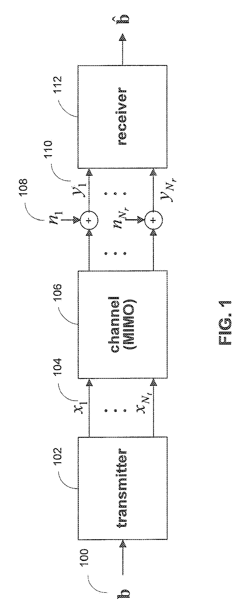
[0047]FIG. 1 shows an illustration of a basic data transmission or storage system in accordance with one embodiment of the present invention. Data, typically grouped into packets, is sent from transmitter 102 to receiver 112. During transmission, the signals may be altered by a transmission medium, represented by channel 106, and additive noise sources 108. Transmitter 102 has Nt outputs 104 and receiver 112 has Nr inputs 110, so channel 106 is modeled as a multiple-input multiple-output (MIMO) system with Nt inputs and Nr outputs. The Nt input and Nr output dimensions may be implemented using multiple time, frequency, or spatial dimensions, or any combination of such dimensions.

[0048]In one embodiment, FIG. 1 represents a wirel...


PUM


Abstract

Systems and methods are provided for decoding signal vectors in multiple-input multiple-output (MIMO) systems, where the receiver has received one or more signal vectors from the same transmitted vector. The symbols of the received signal vectors are combined, forming a combined received signal vector that may be treated as a single received signal vector. The combined signal vector is then decoded using a maximum-likelihood decoder. In some embodiments, the combined received signal vector may be processed prior to decoding. Systems and methods are also provided for computing soft information from a combined signal vector based on a decoding metric. Computationally intensive calculations can be extracted from the critical path and implemented in preprocessors and / or postprocessors.

Description

CROSS-REFERENCE TO RELATED APPLICATIONS[0001]This application claims the benefit under 35 U.S.C. §119(e) of U.S. Provisional Application No. 60 / 820,419, filed Jul. 26, 2006, 60 / 822,294, filed Aug. 14, 2006, and 60 / 822,821, filed Aug. 18, 2006, which are incorporated herein by reference in their entirety.BACKGROUND OF THE INVENTION[0002]This invention relates to a technique for decoding a received signal vector in a multiple-input multiple-output (MIMO) data transmission or storage system, where the receiver may receive multiple instances of the same transmitted signal vector.[0003]In a data transmission or storage system, it is desirable for information, often grouped into packets, to be accurately received at a destination. A transmitter at or near the source sends the information provided by the source via a signal or signal vector. A receiver at or near the destination processes the signal sent by the transmitter. The medium, or media, between the transmitter and receiver, throug...

Claims


Application Information

Patent Timeline
Patent Type & Authority Patents(United States)
IPC IPC(8): H04B7/02
CPCH04B7/0842H04L1/1845H04L1/1819H04L1/189H04L25/0204
Inventor LEE, JUNGWONJANG, WOONG JUNSONG, LEILEI
Owner NXP USA INC
Why Eureka
Try Eureka