Speckle reduction in imaging applications and an optical system thereof

a technology of optical system and imaging application, applied in the field of optical devices, can solve the problems of reducing the quality of displayed images, causing unwanted artificial effects of solid-state light sources,

a technology of optical system and imaging application, applied in the field of optical devices, can solve the problems of reducing the quality of displayed images, causing unwanted artificial effects of solid-state light sources,

US20090303572A1Inactive Publication Date: 2009-12-10TEXAS INSTR INC

Image

  • Speckle reduction in imaging applications and an optical system thereof
  • Speckle reduction in imaging applications and an optical system thereof
  • Speckle reduction in imaging applications and an optical system thereof

Examples


Embodiment Construction

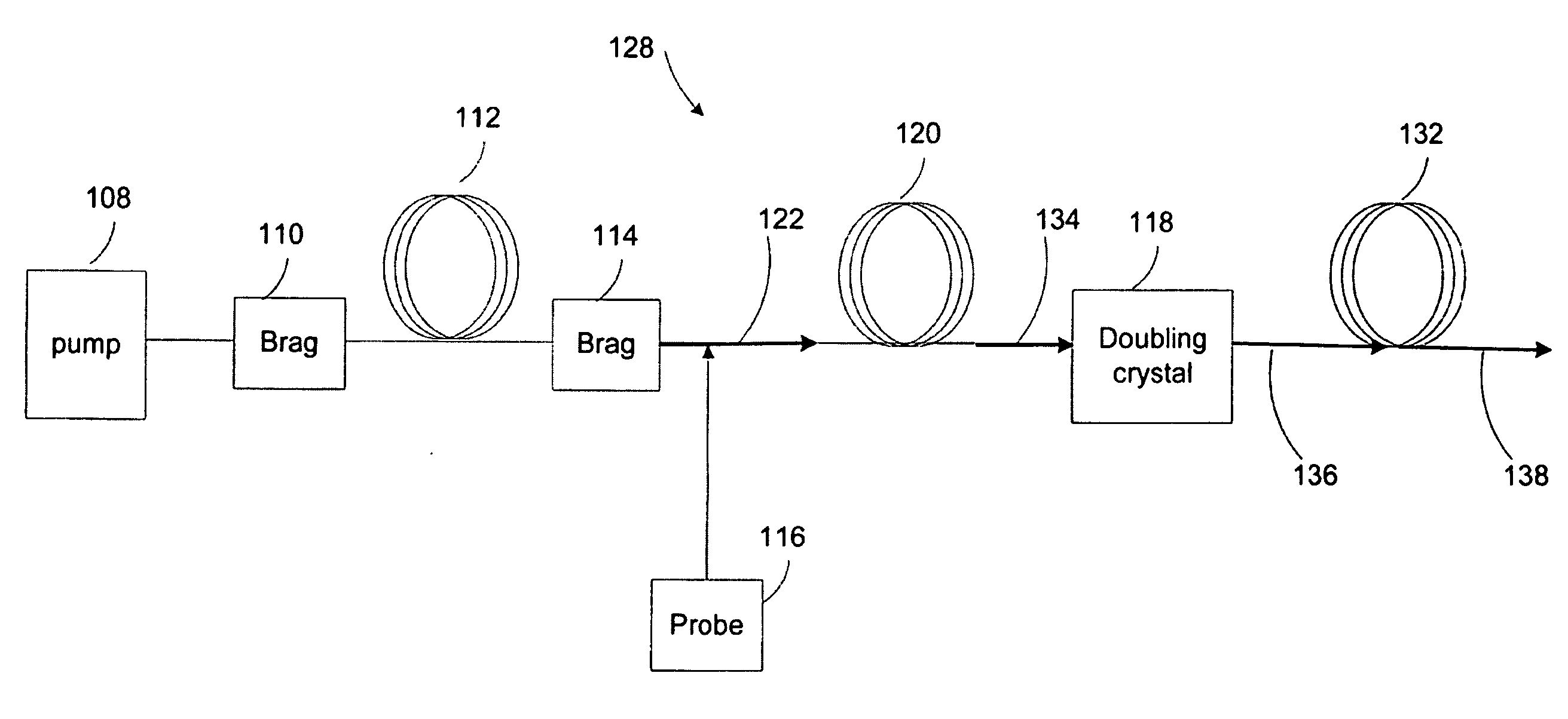
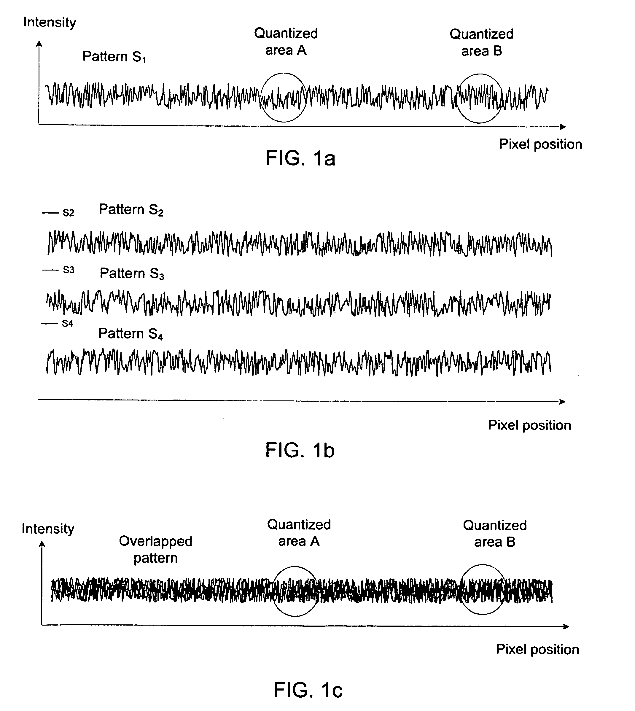
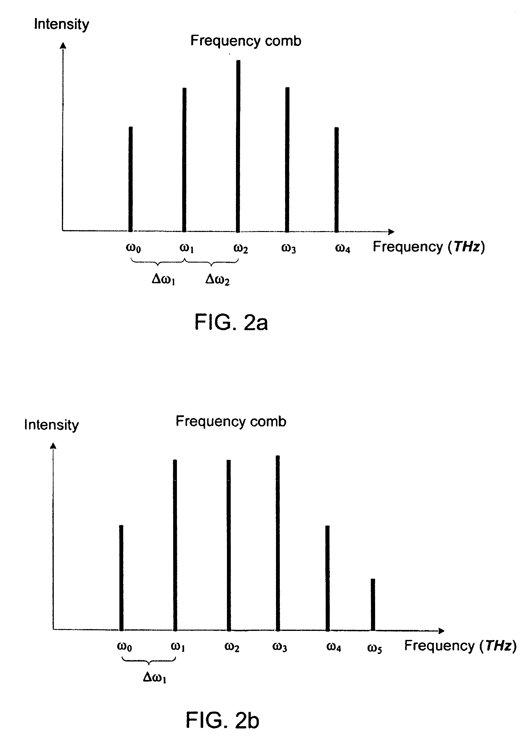
[0025]Disclosed herein is a method of reducing speckle effect in display applications that employ phase-coherent light by using a frequency comb generated from the phase-coherent light. The phase-coherent light in the frequency comb causes separate speckle patterns on the screen. The separate speckle patterns overlap on the screen and average out as a noise background. Also disclosed is an optical structure capable of generating a frequency comb that comprises substantially discrete light lines of different frequencies by using a non-linear optical fiber. As will be detailed afterward, the optical structure can be used independently of the method of speckle reduction.

[0026]The speckle reduction method and the optical structure capable of reducing speckle effect will be discussed in the following, with particular examples where speckle patterns from speckle effect are caused by lasers. However, it will be appreciated by those skilled in the art that the following discussion is for de...


PUM


Abstract

Speckle effect in imaging applications is reduced by generating additional speckle patterns on the screen such that the speckle patterns are overlapped and the overlapped speckle patterns average out on the screen to appear as a noise background to the viewers. The speckle patterns are generated by discrete optical signals of a visible frequency comb. A visible frequency comb having discrete optical signals is generated through modulation-instability processes, phase-conjugation processes, and Bragg-scattering processes using a non-linear optical material and a wavelength converter.

Description

TECHNICAL FIELD OF THE DISCLOSURE[0001]The technical field of this disclosure relates to the art of optical devices; and more particularly to the art of optical systems employing phase-coherent light and methods of using the same for reducing speckle effect in imaging applications.BACKGROUND OF THE DISCLOSURE[0002]In recent years, solid-state light sources and other narrow-wavelength-band and / or polarized light sources capable of producing visible light have drawn significant attention as alternative light sources to traditional light sources for use in imaging systems (such as projection systems). This attention has been due to many advantages of these light sources, such as compact size, greater durability, longer operating life, higher efficiency, and lower power consumption. For example, solid state sources such as LASERs, light-emitting-diodes (LEDs), and pumped non-linear optical crystals are increasingly being used or considered for use in imaging systems, e.g. imaging system...

Claims


Application Information

Patent Timeline
10 Dec 2009
Publication
US20090303572A1
IPC
G02B26/08; H01S3/10
CPC
G02B27/48; G02F1/353; G02F2203/56; H01S3/094003; H01S3/0092; H01S3/0675; H01S3/005
Inventors
GRASSER, REGIS; RADIC, STOJAN